V/SV
Vacuum Relief Valve
- “full lift type” technology valve utilizes only 10% overpressure to reach full lift
- extreme tightness and hence least possible product losses and reduced environmental pollution
- the set pressure is close to the opening pressure which results in best possible pressure management of the system
- very high flow capacity
- the valve pallet is guided within the housing to protect against harsh weather conditions
- can be used in areas subject to explosion hazards
- self draining
- maintenance friendly design
- best technology for API-tanks
Function and Description
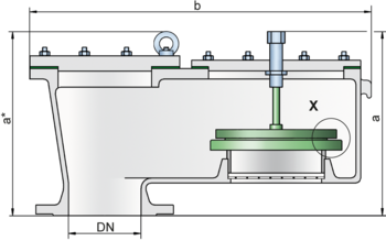
The V/SV type PROTEGO® valve is a highly developed vacuum relief valve with excellent flow performance. It is primarily used as a device for relieving vacuum in tanks, containers and process engineering equipment. The valve offers reliable protection against vacuum, and prevents inbreathing of air close to the set pressure.
The device will start to open as soon as the set pressure is reached and only requires 10% overpressure to full lift. Continuous investments into research and development have allowed PROTEGO® to develop a low pressure valve which has the same opening characteristic as a high pressure safety relief valve. This “full lift type” technology allows the valve to be set just 10% below the maximum allowable working pressure of the tank and still safely vent the required mass flow.
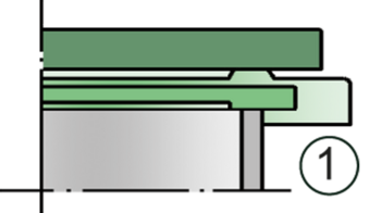
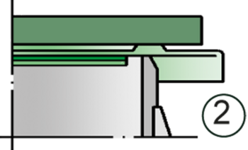
Due to our highly developed manufacturing technology the tank pressure is maintained up to set pressure, with a tightness that is far superior to the conventional standard. This feature is achieved by valve seats made of high quality stainless steel and with precisely lapped valve pallets (1) or with an air cushion seal (2) in conjunction with high quality FEP diaphragm. The valve pallets are also available with a PTFE seal to prevent the valve pallets from sticking when sticky products are used, and they enable the use of corrosive media. After the vacuum is relieved, the valve reseats and provides a tight seal again.
The optimized fluid dynamic design of the valve body and valve pallet is a result of many years of research work, which allow a stable operation of the valve pallet and optimized performance resulting in reduction of product losses.
Design Types and Specifications
There are two different designs:
Vacuum valve in basic design | V/SV - – |
Vacuum valve with heating jacket | V/SV - H |
Additional special devices available upon request
Settings
| Vacuum: | -2.0 mbar | -60 mbar | |
| -0.8 inch W.C. | -24 inch W.C. |
Flow Capacity Chart
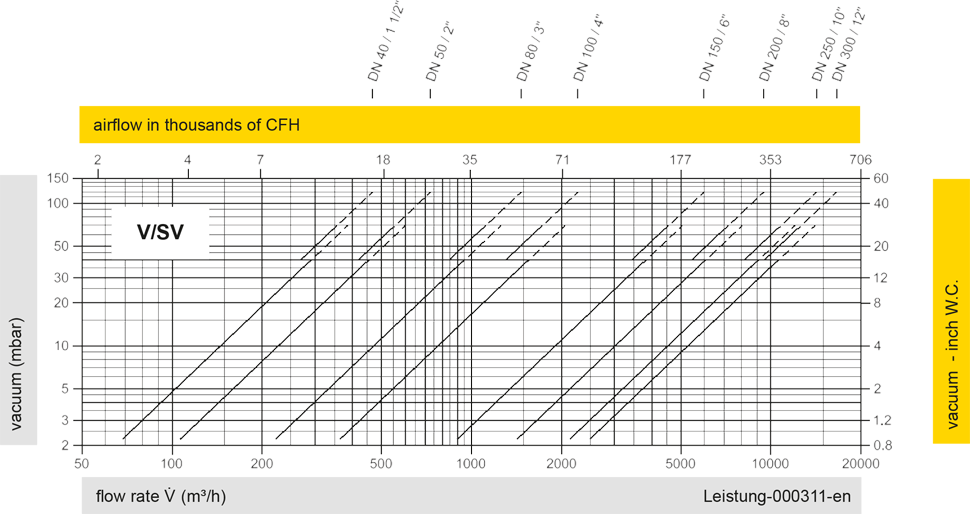
The flow capacity charts have been determined with a calibrated and TÜV certified flow capacity test rig. Volume flow V in (m³/h) and CFH refer to the standard reference conditions of air ISO 6358 (20°C, 1bar). For conversion to other densities and temperatures refer to Sec. 1: “Technical Fundamentals”.