DR/ES-PTFE
In-Line Detonation Flame Arrester for stable detonations and deflagrations in right angle design with shock absorber, unidirectional
- build up of adhesive materials is prevented by the smooth surfaces
- minimum number of FLAMEFILTER® discs due to the effective shock absorber
- quick removal and installation of the complete PROTEGO® flame arrester unit and the individual FLAMEFILTER® discs in the cage
- the modular design enables each individual FLAMEFILTER® discs to be replaced
- offers protection against deflagrations and stable detonations
- the right angle design saves pipe elbows
- ideal for corrosive media
- less soiling of the device lowers service, operating and life-cycle cost
Function and Description
The PROTEGO® DR/ES-PTFE series in-line detonation flame arrester is distinguished by its unique resistance to adhesive and corrosive media. The use of fluoroplastics as a high-tech housing coating and as safety flame arrester element is unique throughout the world. The device represents a further development of PROTEGO® flame arresters DR/ES in a right angle design that have been used and proven for decades in industry. The device protects against deflagrations and stable detonations.
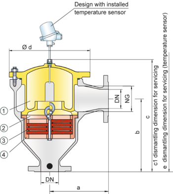
Once a detonation enters the flame arrester, energy is absorbed from the detonation shock wave by the integrated shock absorber (1) before the flame is extinguished in the narrow channel of the PTFE FLAMEFILTER® (3).
The PROTEGO® flame arrester unit (2) consists of several FLAMEFILTER® discs and spacers firmly held in the FLAMEFILTER® cage (4). The gap size and number of FLAMEFILTER® discs are determined by the operating data parameters of the mixture flowing in the line (pressure, temperature). The detonation arrester can be used for explosion group IIA (NEC group D). The standard design is approved at an operating temperature up to +60°C / 140°F and an absolute operating pressure acc. to table 3.
EU conformity according to the currently valid ATEX directive. Approvals according to other national/international regulations on request.
Design Types and Specifications
There are two different designs available:
Basic in-line detonation flame arrester | DR/ES - PTFE – |
In-line detonation flame arrester with integrated temperature sensor* as additional protection against short time burning | DR/ES - PTFE - T |
*Resistance thermometer for device group II, category (1) 2 (GII cat. (1) 2)
Flow Capacity Chart
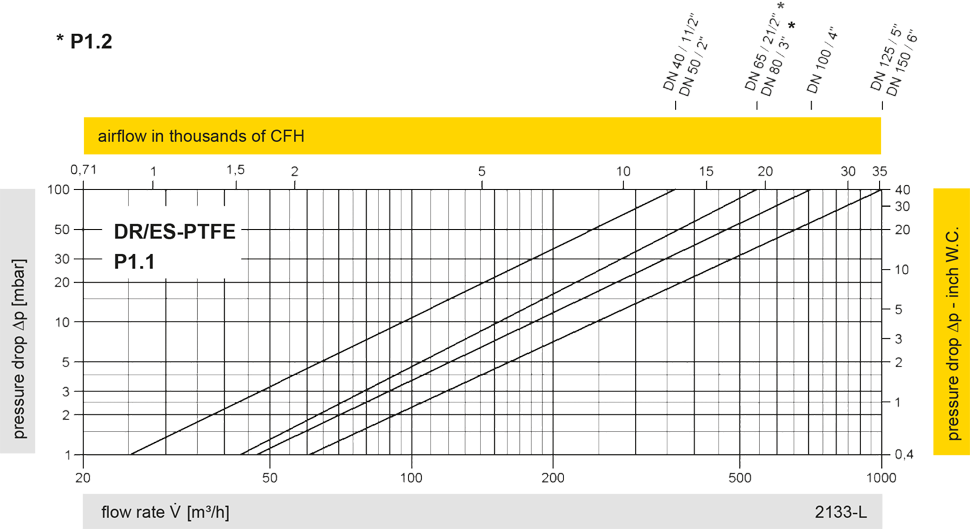
The flow capacity charts have been determined with a calibrated and TÜV certified flow capacity test rig. Volume flow V in (m³/h) and CFH refer to the standard reference conditions of air ISO 6358 (20°C, 1bar). For conversion to other densities and temperatures refer to Sec. 1: “Technical Fundamentals”.