DA-G
In-Line Detonation Flame Arrester for stable detonations and deflagrations in a straight through design, bidirectional
- bi-directional
- modular design
- quick removal and installation of the individual FLAMEFILTER®
- easy maintenance and replacement of the individual FLAMEFILTER®
- various uses possible
- installation of temperature sensors for G 1½ and G 2 possible
- cost-effective spare parts
Function and Description
The PROTEGO® DA-G series is a compact in-line detonation flame arrester for installation in pipes with diameters up to 3“ and is used, for example, in industrial applications such as gas analysis lines.
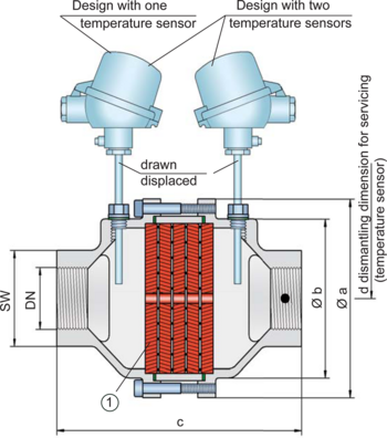
Once a detonation enters the flame arrester, energy is absorbed from the shock wave, and the flame is extinguished in the narrow gaps of the FLAMEFILTER® (1).
The PROTEGO® flame arrester unit consists of several FLAMEFILTER® discs firmly held in a housing. The gap size and number of FLAMEFILTER® discs are determined by the operating data and parameters of the mixture flowing in the line (explosion group, pressure, temperature).
To provide an optimum result between the housing size, number of FLAMEFILTER® discs and their gap size, a device was developed that can be used for all explosion groups - IIA, IIB3 and IIC (NEC Group D, C MESG ≥ 0.65 mm and B). The standard design can be used with an operating temperature of up to +60°C / 140°F and an absolute operating pressure up to 1.1 bar / 15.9 psi. Devices with special approvals for higher pressures (see table 4) and higher temperatures are available upon request.
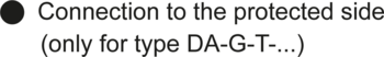
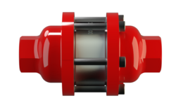
The device is bi-directional and equipped with a threaded connection. This can be adapted to international standards. The detonation arrester can be used at any location in the pipe, regardless of the location of the ignition source.
EU conformity according to the currently valid ATEX directive. Approvals according to other national/international regulations on request.
Design Types and Specifications
There are three different designs available:
Basic design of the DA-G in-line detonation flame arrester, size ½“ to 2“ | DA-G- – |
In-line detonation flame arrester with integrated temperature sensor* as additional protection against short burning from one side, size 1½“ to 2“ | DA-G- T |
In-line detonation flame arrester with two integrated temperature sensors* as additional protection against short time burning from both sides, size 1½“ to 2“ | DA-G- TB |
*Resistance thermometer for device group II, category (1) 2 (GII cat. (1) 2)
Flange connection available upon request
Flow Capacity Chart
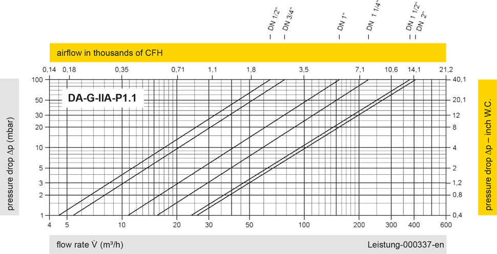
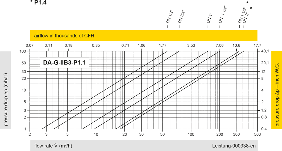
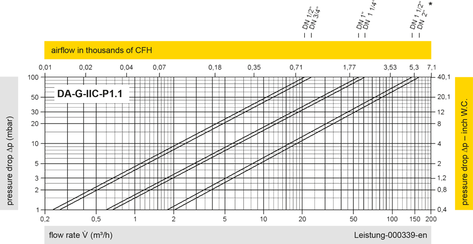
The flow capacity charts have been determined with a calibrated and TÜV certified flow capacity test rig. Volume flow V in (m³/h) and CFH refer to the standard reference conditions of air ISO 6358 (20°C, 1bar). For conversion to other densities and temperatures refer to Sec. 1: “Technical Fundamentals”.