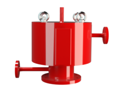
SD/BS-H
Pressure Relief Valve in heat jacketed design
- 10% technology for minimum pressure increase up to full lift
- extreme tightness, resulting in lowest possible product losses and reduced environmental pollution
- set pressure close to opening pressure for optimum pressure maintenance in the system
- high flow capacity
- valve pallet is guided inside the housing to protect against harsh weather conditions
- can be used in areas subject to an explosion hazard
- complete heating jacket up to the flange to avoid ice build-up
- maximum allowable heating medium temperature of 320°C / 608°F (at 6 bar / 87 psi)
- available in a special design with a heatable valve cover
- for low pressure settings, an optimized valve pallet cover prevents the set pressure from being adjusted due to dust deposits or condensate
- sturdy housing design
- available in a special design with lifting device
Function and Description
The SD/BS-H type PROTEGO® valve is a highly developed pressure relief valve with a heating jacket down to the flange. It is primarily used as pressure relief device for vessels and process engineering equipment under difficult operating conditions. This includes extreme weather conditions or products that tend to form polymers at certain temperatures, stick together, or form deposits that negatively influence function (such as bitumen, tar, dust). The valve offers reliable protection against overpressure and prevents excessive loss of product vapors close to the set pressure.
The device will start to open as soon as the set pressure is reached and only requires 10% overpressure to full lift. Continuous investments in and a commitment to research and development have allowed PROTEGO® to develop a low pressure valve which has the same opening characteristic as a high pressure safety relief valve. With this “full lift type” technology, the valve can be set at just 10% below the maximum allowable working pressure of the tank and still safely vent the required mass flow.
Due to our highly developed manufacturing technology, the tank pressure is maintained up to set pressure with a tightness that is far superior to the conventional standard. This feature is achieved by valve seats made of high-grade stainless steel with precisely lapped valve pallets and a sturdy housing design.After the excess pressure is released, the valve re-seats and provides a tight seal again.
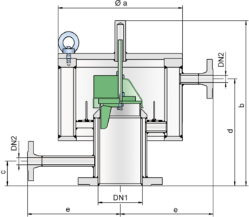
Dimensions
To select the nominal size (DN), use the flow capacity chart on the following page
| DN1 | DN2 | a | b | b | c | d | d | e |
| bis 30 mbar | > 30 mbar | bis 30 mbar | > 30 mbar | |||||
| 80 / 3" | 15 / ½" | 325 / 12.80 | 400 / 15.75 | 515 / 20.28 | 70 / 2.76 | 250 / 9.84 | 390 / 15.35 | 250 / 9.84 |
| 100 / 4" | 15 / ½" | 325 / 12.80 | 400 / 15.75 | 505 / 19.88 | 60 / 2.36 | 250 / 9.84 | 380 / 14.96 | 250 / 9.84 |
| 150 / 6" | 15 / ½" | 405 / 15.94 | 460 / 18.11 | 595 / 23.43 | 60 / 2.36 | 315 / 12.40 | 470 / 18.50 | 290 / 11.42 |
| 200 / 8" | 15 / ½" | 510 / 20.08 | 470 / 18.50 | 575 / 22.64 | 65 / 2.56 | 305 / 12.01 | 445 / 17.52 | 340 / 13.39 |
Material selection for housing
| Design | A | B |
| Housing | Steel | Stainless Steel |
| Heating Jacket | Steel | Stainless Steel |
| Valve Seat | Stainless Steel | Stainless Steel |
Material selection for pressure valve pallet
| Design | A | B | C |
| Pressure range [mbar] [inch W.C.] | +5,0 up to +25 +2 up to +10 | >+10 up to +30 >+4 up to +12 | >+30 up to +210 >+12 up to +84 |
| Valve pallet | Aluminium | Stainless Steel | Stainless Steel |
| Valve pallet hood | Stainless Steel | Stainless Steel | - |
| Sealing | Metal to Metal | Metal to Metal | Metal to Metal |
Flange connection type
| EN 1092-1; Form B1 |
| ASME B16.5 CL 150 R.F. |
Design Types and Specifications
The valve pallet is weight-loaded. Starting at a set pressure of 30 mbar, a vane guide is also used.
Pressure valve in basic design with heating jacket | SD/BS - H |
Additional special devices available upon request.
Settings
| Pressure: | +5.0 mbar | +210 mbar | |
| +2.0 inch W.C. | +84 inch W.C. |
Flow Capacity Chart
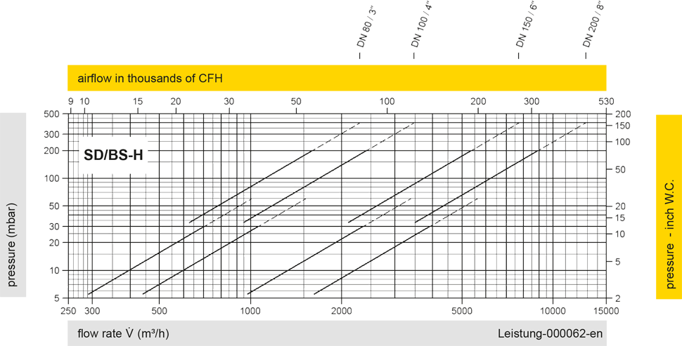
The flow capacity charts have been determined with a calibrated and TÜV certified flow capacity test rig. Volume flow V in (m³/h) and CFH refer to the standard reference conditions of air ISO 6358 (20°C, 1bar). For conversion to other densities and temperatures refer to Sec. 1: “Technical Fundamentals”.