FA-E-IIA1
In-Line Deflagration Flame Arrester for biogas, sewage gas and landfill gas, eccentric design, bidirectional, endurance burning proof (under atmospheric conditions up to DN 200 / 8“)
- state of the art design for bio-, sewage- and landfill gas applications
- eccentric design prevents condensate build up
- offers a wide range of applications
- special design for elevated operating pressures available
- modular design enables each individual FLAMEFILTER® to be replaced
- easy to maintain and the FLAMEFILTER® can be quickly removed and installed
- eccentric design eases installation close to floors and walls
- provides protection against deflagrations and endurance burning for explosion group IIA1- methane (former designation Expl.gr. I)
- bidirectional operation as well as any direction of flow and installation position
- endurance burning proof under atmospheric conditions up to DN 200 / 8” and therefore the installation of temperature sensors is not required
- installation of temperature sensors is possible
- cost efficient spare parts
Function and Description
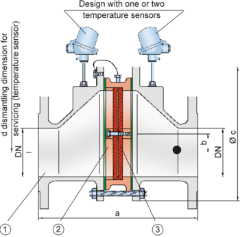
The PROTEGO® FA-E-IIA1 series of in-line deflagration flame arresters is designed with an eccentric housing to automatically drain condensate build up in the housing. The PROTEGO® FA-E-IIA1 in-line flame arrester was specially developed for bio-, sewage- and landfill-gas applications. The application as an endurance burning proof in-line device under atmospheric conditions without extensive temperature monitoring is of advantage. Due to its eccentric design and in contrast to conventional concentric flame arresters the device can be installed in pipelines that run close to floors or walls. When installing the deflagration flame arrester make sure that the distance between potential ignition sources and the location of the installed device does not exceed the L/D ratio (pipe length/pipe diameter) for which the device was approved. According to EN ISO 16852 the installation limits are (L/D)max ≤ 50 for deflagration flame arresters for explosion group IIA1- methane (former designation Expl.gr. I).
The deflagration flame arrester is symmetric and offers bidirectional flame transmission protection. The arrester essentially consists of two housing parts (1) and the PROTEGO® flame arrester unit (2) in the center. The PROTEGO® flame arrester unit is modular and consist of several FLAMEFILTER® (3) and spacers firmly held in a FLAMEFILTER® casing. The PROTEGO® FA-E-IIA1 flame arrester protects against deflagrations and endurance burning (under atmospheric condition up to DN 200 / 8”) of explosion group IIA1 - methane (former designation Expl.gr. I). The PROTEGO® FA-E devices for substances of explosion groups IIA, IIB3 and IIC (NEC groups B, C, and D) are shown on separate pages.
The standard design can be used up to an operating temperature of +60°C / 140°F and up to an absolute operating pressure of 1.1 bar / 15.9 psi. Numerous devices with special approvals can be obtained for higher temperatures and pressures.
EU conformity according to the currently valid ATEX directive. Approvals according to other national/international regulations on request.
Dimensions
To select the nominal size (DN), please use the flow capacity charts on the following pages
| DN | 25 / 1" | 32 / 1¼" | 40 / 1½" | 50 / 2" | 65 / 2½" | 80 / 3" | 100 / 4" | 125 / 5" | 150 / 6" | 200 / 8" | 250 / 10" | 300 / 12" |
| a | 304 / 11.97 | 304 / 11.97 | 310 / 12.20 | 314 / 12.36 | 360 / 14.17 | 364 / 14.33 | 370 / 14.57 | 435 / 17.09 | 440 / 17.32 | 450 / 17.72 | 480 / 18.90 | 500 / 16.69 |
| b | 29 / 1.14 | 29 / 1.14 | 29 / 1.14 | 29 / 1.14 | 38 / 1.49 | 38 / 1.49 | 39 / 1.53 | 65 / 2.56 | 65 / 2.56 | 55 / 2.17 | 58 / 2.28 | 60 / 2.36 |
| c | 185 / 7.28 | 185 / 7.28 | 210 / 8.27 | 210 / 8.27 | 250 / 9.84 | 250 / 9.84 | 275 / 10.83 | 385 / 15.16 | 385 / 15.16 | 450 / 17.72 | 500 / 19.69 | 575 / 22.64 |
| d | 400 / 15.75 | 400 / 15.75 | 410 / 16.14 | 410 / 16.14 | 440 / 16.14 | 440 / 16.14 | 460 / 18.11 | 520 / 20.47 | 520 / 20.47 | 540 / 21.26 | 570 / 22.44 | 600 / 23.62 |
Material selection for housing
| Design | B | C | |
| Housing | Steel | Stainless Steel | |
| Gasket | PTFE | PTFE | |
| Flame arrester unit | A, B | B |
Material combinations of flame arrester unit
| Design | A | B |
| FLAMEFILTER® cage | Steel | Stainless Steel |
| FLAMEFILTER®* | Stainless Steel | Stainless Steel |
| Spacers | Stainless Steel | Stainless Steel |
Selection of explosion group
| MESG | Expl. Gr. (IEC / CEN) |
| ≥ 1.14 mm | IIA1 (I)* |
Selection of max. operating pressure
| Expl.Gr. | DN | 25 / 1" | 32 / 1¼" | 40 / 1½" | 50 / 2" | 65 / 2½" | 80 / 3" | 100 / 4" | 125 / 5" | 150 / 6" | 200 / 8" | 250 / 10" | 300 / 12" |
| IIA1 (I) | Pmax | 1,9 / 27.5 | 1,9 / 27.5 | 1,9 / 27.5 | 1,9 / 27.5 | 1,9 / 27.5 | 1,9 / 27.5 | 1,9 / 27.5 | 1,9 / 27.5 | 1,9 / 27.5 | 1,9 / 27.5 | 1,9 / 27.5 | 1,9 / 27.5 |
Specification of max. operating temperature
| ≤ 60°C / 140°F | Tmaximum allowable operating temperature in °C |
| - | Designation |
Flange connection type
| EN 1092-1; Form B1 |
| ASME B16.5 CL 150 R.F. |
Design Types and Specifications
There are three different designs:
Basic in-line deflagration flame arrester | FA-E - – |
In-line deflagration flame arrester with integrated temperature sensor* as additional protection against short-time burning from one side | FA-E - T |
In-line deflagration flame arrester with two integrated temperature sensors* for additional protection against short-time burning from both sides | FA-E - TB |
Additional special devices available upon request
*Resistance thermometer for device group II, category (1) 2 (GII cat. (1) 2)
Flow Capacity Chart
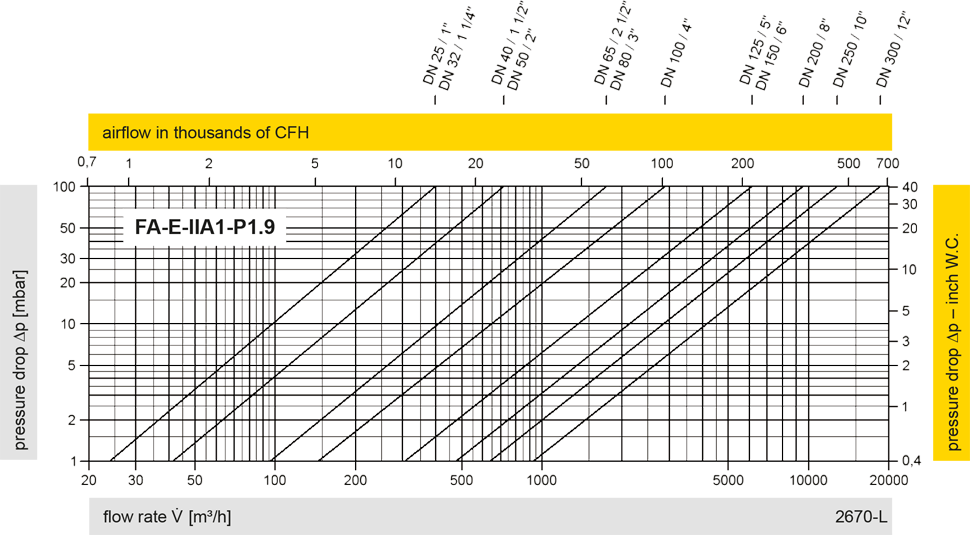
The flow capacity charts have been determined with a calibrated and TÜV certified flow capacity test rig. Volume flow V in (m³/h) and CFH refer to the standard reference conditions of air ISO 6358 (20°C, 1bar). For conversion to other densities and temperatures refer to Sec. 1: “Technical Fundamentals”.