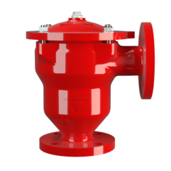
DR/ES
In-Line Detonation Flame Arrester for stable detonations and deflagrations in right angle design with shock absorber, unidirectional
- minimum number of FLAMEFILTER® discs due to the effective shock absorber
- quick removal and installation of the complete PROTEGO® flame arrester unit and FLAMEFILTER® discs in the cage
- due to modular design the FLAMEFILTER® discs can be individually replaced
- the right angle design saves pipe elbows
- extended application range for higher operating temperatures and pressures
- minimum pressure loss and hence low operating and lifecycle cost
- cost efficient spare parts
Function and Description
The PROTEGO® DR/ES in-line detonation flame arrester has been used for decades in industrial plant construction because its right angle design offers advantages towards maintenance and costs in comparison to most straight designs.
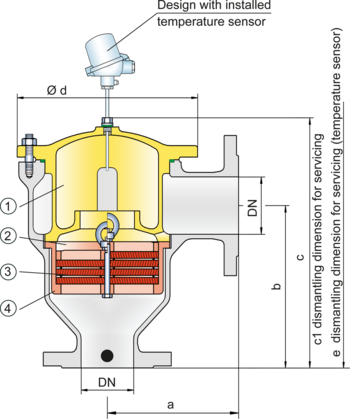
Once a detonation enters the device, energy is absorbed from the detonation shock wave by the integrated shock absorber (1) before the flame is extinguished in the narrow gaps of the FLAMEFILTER® (3).
The PROTEGO® flame arrester unit (2) consists of several FLAMEFILTER® discs and spacers firmly held in the FLAMEFILTER® cage (4). The gap size and number of FLAMEFILTER® discs are determined by the operating data of the mixture flowing in the line (explosion group, pressure, temperature). This device is approved for explosion groups from IIA to IIB3 (NEC group D to C MESG ≥ 0.65 mm).
The standard design is approved at an operating temperature up to +60°C / 140°F and an absolute operating pressure up to 1.2 bar / 17.4 psi. Devices with special approvals can be obtained for higher pressures and higher temperatures upon request.
EU conformity according to the currently valid ATEX directive. Approvals according to other national/international regulations on request.
Dimensions
To select the nominal size (DN), please use the flow capacity charts on the following pages
| DN | 25 / 1" | 32 / 1¼“ | 40 / 1½“ | 50 / 2" | 65 / 2½“ | 80 / 3“ | 100 / 4“ | 125 / 5" | 150 / 6" | 200 / 8" |
| a | 125 / 4.92 | 125 / 4.92 | 153 / 6.02 | 155 / 6.10 | 198 / 7.80 | 200 / 7.87 | 250 / 9.84 | 332 / 13.07 | 335 / 13.19 | 425 / 16.73 |
| b | 140 / 5.51 | 140 / 5.51 | 183 / 7.20 | 185 / 7.28 | 223 / 8.78 | 225 / 8.86 | 290 / 11.42 | 357 / 14.06 | 360 / 14.07 | 505 / 19.88 |
| c | 210 / 8.27 | 210 / 8.27 | 290 / 11.42 | 290 / 11.42 | 365 / 14.37 | 365 / 14.37 | 415 / 16.34 | 535 / 21.06 | 535 / 21.06 | 810 / 31.89 |
| c1 | 285 / 11.22 | 285 / 11.22 | 395 / 15.55 | 395 / 15.55 | 500 / 19.69 | 500 / 19.69 | 595 / 23.43 | 750 / 29.53 | 750 / 29.53 | 1230 / 48.43 |
| d | 150 / 5.91 | 150 / 5.91 | 210 / 8.27 | 210 / 8.27 | 275 / 10.83 | 275 / 10.83 | 325 / 12.80 | 460 / 18.11 | 460 / 18.11 | 620 / 24.41 |
| e | 495 / 19.49 | 495 / 19.49 | 600 / 23.62 | 600 / 23.62 | 705 / 27.76 | 705 / 27.76 | 795 / 31.30 | 950 / 37.40 | 950 / 37.40 | 1435 / 56.50 |
Material selection for housing
| Design | B | C | D |
| Housing | Steel | Stainless Steel | Hastelloy |
| Heating jacket (DR / ES-H-(T)-...) | Steel | Stainless Steel | Stainless Steel |
| Cover with shock absorber | Steel | Stainless Steel | Hastelloy |
| O-Ring | FPM* | PTFE | PTFE |
| Flame arrester unit | A | C, D | E |
Material combinations of flame arrester unit
| Design | A | C | D | E |
| FLAMEFILTER® cage | Steel | Stainless Steel | Stainless Steel | Hastelloy |
| FLAMEFILTER®* | Stainless Steel | Stainless Steel | Hastelloy | Hastelloy |
| Spacer | Stainless Steel | Stainless Steel | Hastelloy | Hastelloy |
Selection of explosion group
| MESG | Expl. Gr. (IEC / CEN) | Gas Group (NEC) |
| > 0,90 mm | IIA | D |
| ≥ 0,65 mm | IIB3 | C |
Selection of max. operating pressure
| Expl. Gr. | DN | 25 / 1" | 32 / 1¼" | 40 / 1½" | 50 / 2" | 65 / 2½" | 80 / 3" | 100 / 4" | 125 / 5" | 150 / 6" | 200 / 8“ |
| IIA | Pmax | 4,0 / 58.0 | 4,0 / 58.0 | 4,0 / 58.0 | 4,0 / 58.0 | 2,9 / 42.1 | 2,9 / 42.1 | 2,0 / 29.0 | 2,0 / 29.0 | 2,0 / 29.0 | 1,2 / 17.4 |
| IIB3 | Pmax | 3,0 / 43.5 | 3,0 / 43.5 | 2,0 / 29.0 | 2,0 / 29.0 | 2,0 / 29.0 | 2,0 / 29.0 | 1,5 / 21.7 | 1,4 / 20.3 | 1,4 / 20.3 | 1,1 / 20.3 |
Specification of max. operating temperature
| ≤ 60°C / 140°F | Tmaximum allowable operating temperature in °C |
| - | Designation |
Flange connection type
| EN 1092-1; Form B1 |
| ASME B16.5 CL 150 R.F. |
Design Types and Specifications
There are four different designs available:
Basic design of the detonation arrester | DR/ES- – - – |
In-line detonation flame arrester with integrated temperature sensor* as additional protection against short time burning | DR/ES- T - – |
In-line detonation flame arrester with heating jacket | DR/ES- H - – |
In-line detonation flame arrester with integrated temperature sensor* against short time burning and heating jacket | DR/ES- H - T |
*Resistance thermometer for device group II, category (1) 2 (GII cat. (1) 2)
Flow Capacity Chart
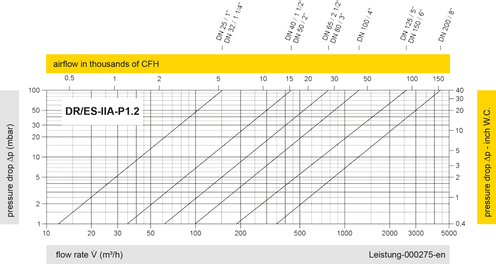
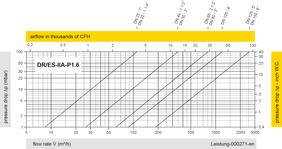
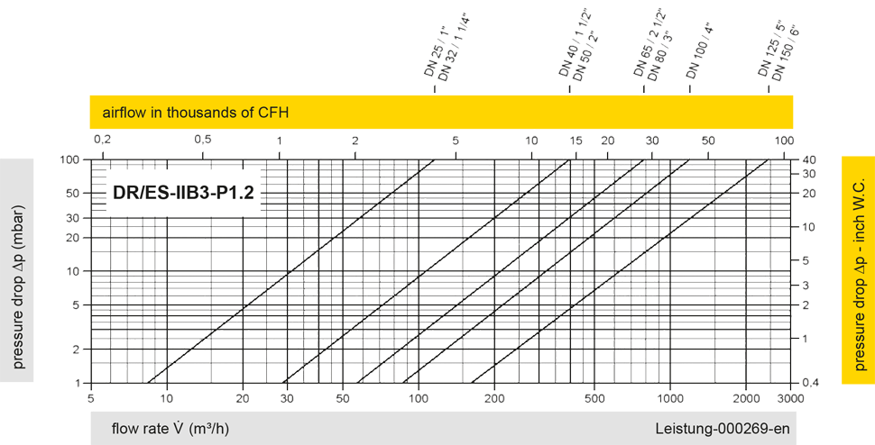
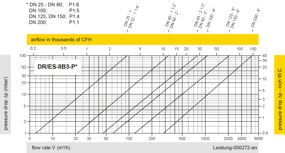
The flow capacity charts have been determined with a calibrated and TÜV certified flow capacity test rig. Volume flow V in (m³/h) and CFH refer to the standard reference conditions of air ISO 6358 (20°C, 1bar). For conversion to other densities and temperatures refer to Sec. 1: “Technical Fundamentals”.
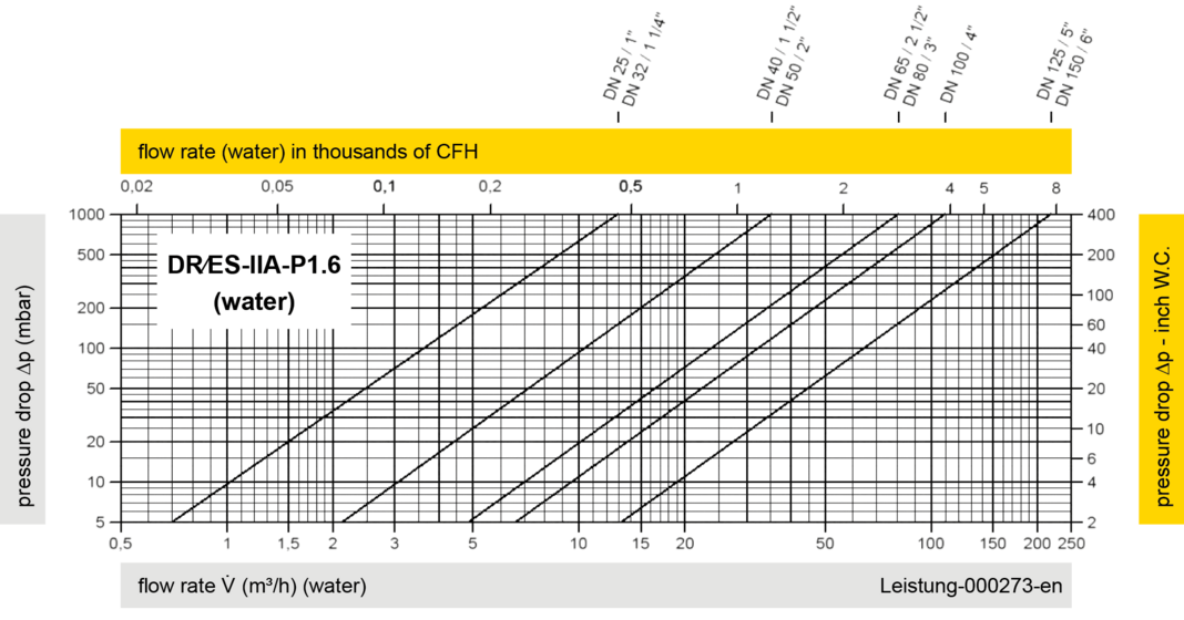
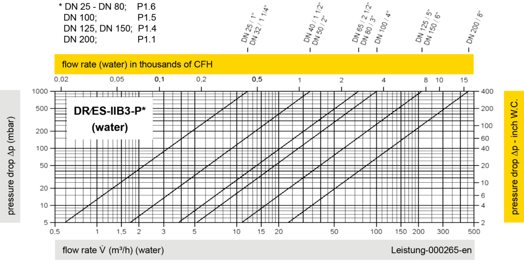

The volume flow V in m³/h was determined with water according to DIN EN 60534 at a temperature Tn = 20°C and an atmospheric pressure pn = 1,013 bar, kinematic viscosity v = 10-6 m²/s