LDA-W
In-Line Liquid Detonation Flame Arrester for filling lines - external installation
- easily accessible due to external installation
- low risk of contamination
- low pressure loss
- provides protection against deflagrations and stable detonations
- useable for nearly all flammable liquids
- meets TRGS* requirements
- can also be used as a dirt catcher in a maintenance friendly design
Function and Description
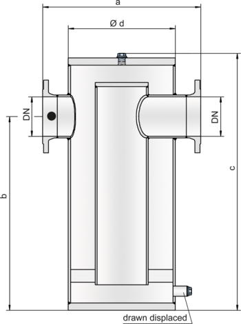
The PROTEGO® LDA-W liquid detonation flame arrester was developed for storage container filling lines that are not continuously filled with product and sometimes contain a combustible mixture. The device is installed outside the container in the filling line. If the explosive atmosphere is ignited, the device prevents the combustion from transferring into the tank. The PROTEGO® LDA-W series of liquid detonation flame arresters function according to the siphon principle in which the liquid product serves as a barrier against flame propagation.
When a highly accelerated pipe deflagration or detonation occurs, the combustion pressure and flame propagation speed are substantially reduced by the design and converted into a low-energy deflagration that is then stopped by the remaining immersion liquid.
The application range for the device is a product vapor / air mixture temperature of up to +60°C / 140°F and an absolute pressure of up to 1.1 bar / 15.9 psi. This covers all possible operating conditions of empty lines for flammable liquids. The liquid detonation arrester is designed for pressures of up to 10 bar / 145 psi, resists explosion pressure, and provides protection for almost all flammable liquids. The device is approved for explosion groups IIA to IIB3 (NEC group D to C MESG ≥ 0.65 mm). Special designs with a cleaning cover for highly viscous and contaminated liquids are available.
EU conformity according to the currently valid ATEX directive. Approvals according to other national/international regulations on request.
Flow Capacity Chart
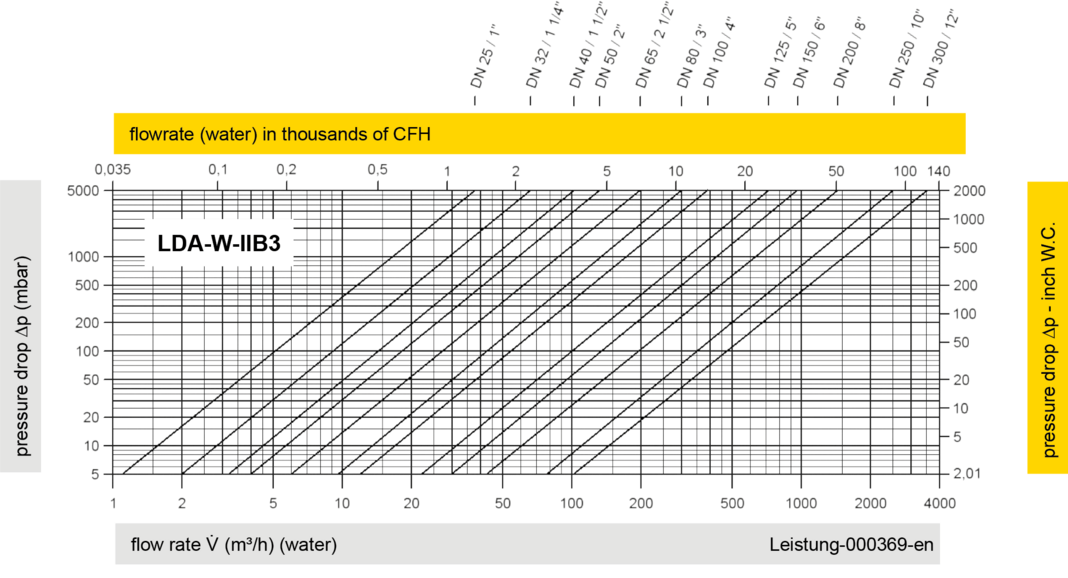

The volume flow V in m³/h was determined with water according to DIN EN 60534 at a temperature Tn = 20°C and an atmospheric pressure pn = 1,013 bar, kinematic viscosity v = 10-6 m²/s