DR/SBW
In-Line Detonation Flame Arrester for stable detonations and deflagrations in a straight through design with shock absorber, bidirectional
- particularly service-friendly design
- minimum number of FLAMEFILTER® discs due to use of effective shock absorber
- the modular design enables each individual FLAMEFILTER® discs to be exchanged
- bidirectional operation as well as any flow direction and installation position
- expanded application range for higher operating temperatures and pressures
- installation of temperature sensors possible
- minimum pressure loss and hence low operating and lifecycle cost
- cost efficient spare parts
Function and Description
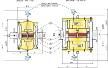
In the development of the PROTEGO® DR/SBW in-line Detonation flame arrester, special effort was made to ease future maintenance of the flame arresters. The PROTEGO® flame arrester unit (5) can be removed and cleaned within moments without having to disassemble the piping. The effective shock absorber of the device and elaborate housing geometry reduces the number of FLAMEFILTER® discs to a minimum.
The device is symmetrical and offers bidirectional flame arresting protecting from stable detonations and deflagrations.The flame arrester consists of a double-jacket housing (1) with two integrated shock absorbers (2) with the PROTEGO® flame arrester unit in the center. The PROTEGO® flame arrester unit consists of several FLAMEFILTER® discs (4) and spacers firmly held in a FLAMEFILTER® cage (3). The number of FLAMEFILTER® discs and their gap size depends on the arrester‘s conditions of use. By indicating the operating parameters such as the temperature, pressure and explosion group and the composition of the fluid, the optimum in-line detonation flame arrester can be selected. The PROTEGO® DR/SBW series of flame arresters is available for explosion groups IIA to IIB3 (NFPA group D to C MESG ≥ 0.65 mm).
The standard design is approved at an operating temperature up to +60°C / 140°F and an absolute operating pressure acc. to table 3. Devices with special approvals can be obtained for higher pressures and higher temperatures upon request.
Type-approved in accordance with the current ATEX Directive and as well as other international standards.
Dimensions
To select the nominal size (DN) and nominal width (NG), please use the flow capacity charts on the following pages
| DN | 50 / 2" | 80 / 3" | 100 / 4" | 150 / 6" | 200 / 8" | 250 / 10" | 300 / 12" | 350 / 14" | 400 / 16" |
| NG | 150 / 6" | 150 / 6" | 200 / 8" | 300 / 12" | 500 / 20" | 500 / 20" | 600 / 24" | 700 / 28" | 800 / 32" |
| a | 225 / 8.86 | 225 / 8.86 | 275 / 10.83 | 350 / 13.78 | 550 / 21.65 | 550 / 21.65 | 725 / 28.54 | 800 / 31.50 | 825 / 32.48 |
| b | 210 / 8.27 | 210 / 8.27 | 220 / 8.66 | 290 / 11.42 | 525 / 20.67 | 525 / 20.67 | 590 / 23.23 | 655 / 25.78 | 725 / 28.54 |
| b1* | 325 / 12.80 | 325 / 12.80 | 360 / 14.17 | 475 / 18.70 | 835 / 32.87 | 835 / 32.87 | 960 / 37.80 | 1075 / 42.32 | 1215 / 47.83 |
| c | 395 / 15.55 | 395 / 15.55 | 410 / 16.14 | 475 / 18.70 | 630 / 24.80 | 630 / 24.80 | 700 / 27.56 | 765 / 30.12 | 835 / 32.87 |
| c1* | 450 / 17.72 | 450 / 17.72 | 465 / 18.31 | 530 / 20.87 | 730 / 28.74 | 730 / 28.74 | 800 / 31.50 | 865 / 34.06 | 935 / 36.81 |
| d | 275 / 10.83 | 275 / 10.83 | 325 / 12.80 | 460 / 18.11 | 840 / 33.07 | 840 / 33.07 | 1000 / 39.37 | 1150 / 45.28 | 1250 / 49.21 |
c1 dismantling dimension for servicing (temperature sensor)
Material selection for housing
| Design | A | B | C |
| Housing | Steel | Stainless Steel | Hastelloy |
| Heating jacket (DR / SBW-H-(T)-...) | Steel | Stainless Steel | Stainless Steel |
| Cover with shock absorber | Steel | Stainless Steel | Hastelloy |
| Gasket | FPM* | PTFE | PTFE |
| Flame arrester unit | A | C, D | E |
Material combinations of flame arrester unit
| Design | A | C | D | E |
| FLAMEFILTER® cage | Steel | Stainless Steel | Stainless Steel | Hastelloy |
| FLAMEFILTER®* | Stainless Steel | Stainless Steel | Hastelloy | Hastelloy |
| Spacer | Stainless Steel | Stainless Steel | Hastelloy | Hastelloy |
Selection of explosion group
| MESG | Expl. Gr. (IEC / CEN) | Gas Group (NEC) |
| > 0,90 mm | IIA | D |
| ≥ 0,65 mm | IIB3 | C |
Selection of max. operating pressure
| DN | 50 / 2" | 80 / 3" | 100 / 4" | 150 / 6" | 200 / 8" | 250 / 10" | 300 / 12" | 350 / 14" | 400 / 16" | ||
| NG | 150 / 6" | 150 / 6" | 200 / 8" | 300 / 12" | 500 / 20" | 500 / 20" | 600 / 24" | 700 / 28" | 800 / 32" | ||
| Expl. Gr. | IIA | Pmax | 4 / 58 | 4 / 58 | 3 / 43.5 | 3 / 43.5 | 1.6 / 23.2 | 1.6 / 23.2 | 1.1 / 15.9 | 1.1 / 15.9 | 1.1 / 15.9 |
| Expl. Gr. | IIB3 | Pmax | 1.7 / 24.6 | 1.7 / 24.6 | 1.7 / 24.6 | 1.7 / 24.6 | 1.2 / 17.4 | 1.2 / 17.4 | 1.1 / 15.9 | 1.1 / 15.9 | 1.1 / 15.9 |
Specification of max. operating temperature
| ≤ 60°C / 140°F | Tmaximum allowable operating temperature in °C |
| - | Designation |
Flange connection type
| EN 1092-1; Form B1 |
| ASME B16.5 CL 150 R.F. |
Design Types and Specifications
There are four different designs available:
Basic in-line detonation flame arrester | DR/SBW- – - – |
In-line detonation flame arrester with integrated temperature sensor* as additional protection against short time burning of one side | DR/SBW- T - – |
In-line detonation flame arrester with two integrated temperature sensors* as additional protection against short time burning from both sides | DR/SBW- TB - – |
In-line detonation flame arrester with heating jacket | DR/SBW- H - |
Additional special flame arresters upon request
*Resistance thermometer for device group II, category (1) 2 (GII cat. (1) 2)
Flow Capacity Chart
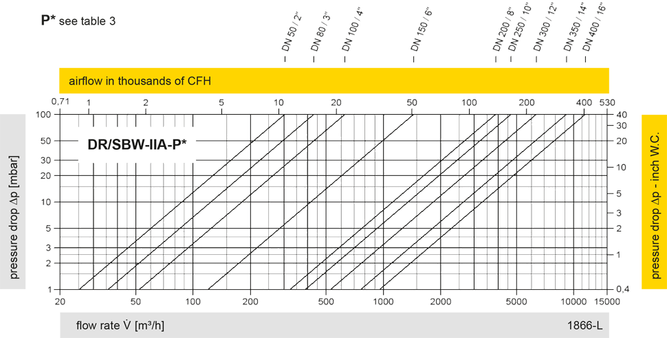
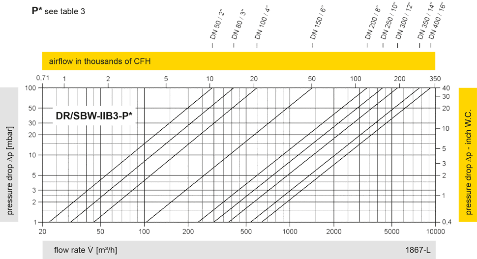
The flow capacity charts have been determined with a calibrated and TÜV certified flow capacity test rig. Volume flow V in (m³/h) and CFH refer to the standard reference conditions of air ISO 6358 (20°C, 1bar). For conversion to other densities and temperatures refer to Sec. 1: “Technical Fundamentals”.