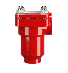
DR/ES, DN 1/4 - 3/4
In-Line Detonation Flame Arrester for stable detonations and deflagrations in right angle design, unidirectional
- compact design
- minimum number of FLAMEFILTER® discs due to shock absorber technology and optimal geometry
- the device can be serviced without disconnecting the pipe
- the individual FLAMEFILTER® can be quickly removed and installed
- provides protection from deflagration and stable detonation
- through right angle design no pipe elbows are needed
- works for nearly any flammable gas and gas mixture
- low life-cycle cost
- cost efficient spare parts
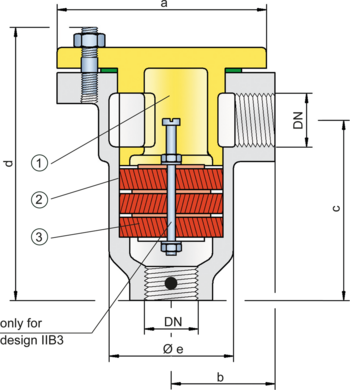
Function and Description
The PROTEGO® DR/ES series in-line detonation flame arrester with connection size up to ¾“ is ideal for installation in small pipes and to protect equipment such as gas analyzers. The device protects against deflagrations and stable detonations. It can be installed anywhere in the pipe no matter what the distance is from the potential ignition source. The small and compact flame arrester has a right angle design.
Once a detonation enters the flame arrester, energy is absorbed from the detonation shock wave by diversion mainly through the shock absorber (1) before the flame is extinguished in the narrow gaps of the FLAMEFILTER® (3). The PROTEGO® flame arrester unit (2) consists of several FLAMEFILTER® discs and spacers (for explosion group IIC - NEC group B) whose gap size and number is determined by the operating parameters of the processed fluid (explosion group, pressure, temperature). This device is available for explosion groups IIB3 and IIC (NEC group C MESG ≥ 0.65 mm and B).
This in-line detonation flame arrester functions unidirectional and is equipped with a threaded connection. The thread can be adapted to international standards. The standard design is approved at an operating temperature up to +60°C / 140°F and an absolute operating pressure acc. to table 3. Devices with special approvals can be obtained for higher pressures and higher temperatures upon request.
EU conformity according to the currently valid ATEX directive. Approvals according to other national/international regulations on request.
Flow Capacity Chart
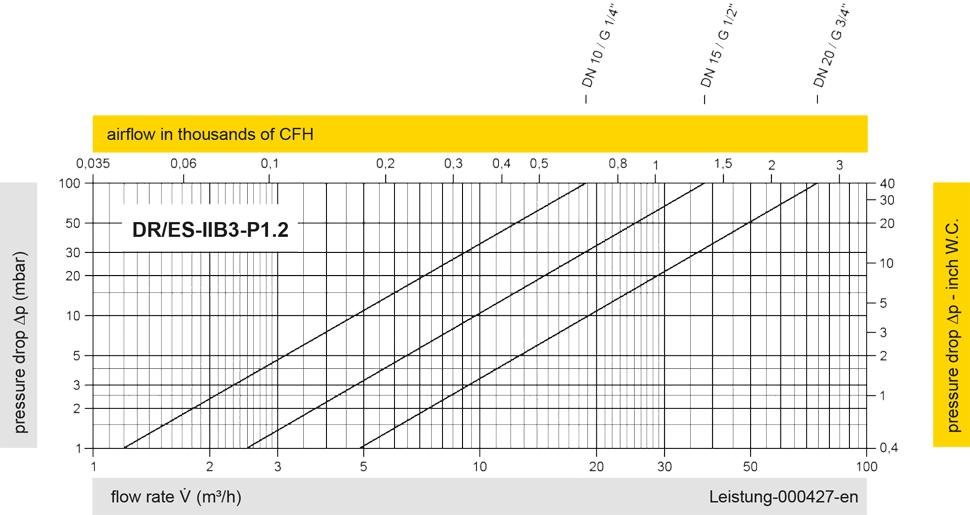
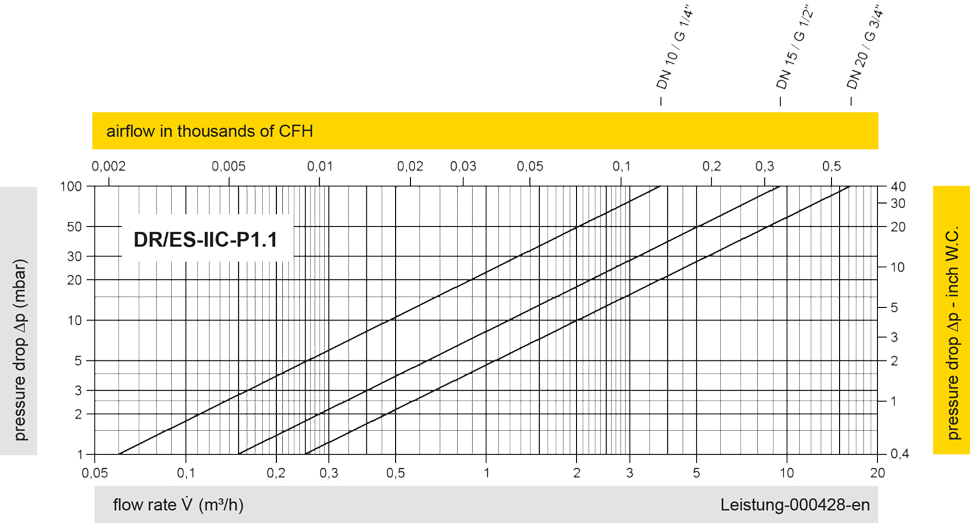
The flow capacity charts have been determined with a calibrated and TÜV certified flow capacity test rig. Volume flow V in (m³/h) and CFH refer to the standard reference conditions of air ISO 6358 (20°C, 1bar). For conversion to other densities and temperatures refer to Sec. 1: “Technical Fundamentals”.