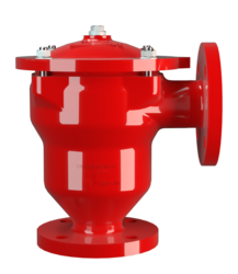
DR-UN
In-Line Detonation Flame Arrester for stable detonations and deflagrations in right angle design with shock absorber, unidirectional
- same dimensions as the PROTEGO® DR/U, therefore replacement possible without converting the piping
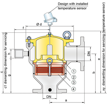
- the suspended FLAMEFILTER® cage (4) enables quick removal and installation of the complete PROTEGO® flame arrester unit and then replacing the individual FLAMEFILTER®
- modular design and optimum availability of spare parts guarantee fast maintenance
- only three FLAMEFILTER® discs due to shock absorber technology
- low pressure loss results in low operating and lifecycle costs
- cost efficient spare parts
Function and Description
The PROTEGO® DR-UN in-line detonation flame arrester are used to secure potentially explosive plants against pipe deflagrations and stable detonations. In the right-angle design and with the PROTEGO® DR/U identical dimensions, the PROTEGO® DR-UN offers considerable maintenance and cost benefits.
Once a detonation enters the device, energy is absorbed from the detonation shock wave by the integrated shock absorber (1) before the flame is extinguished in the narrow gaps of the FLAMEFILTER® (3).
The PROTEGO® flame arrester unit (2) consists of several FLAMEFILTER® discs and spacers firmly held in the FLAMEFILTER® cage (4). The gap size and number of FLAMEFILTER® discs are determined by the operating data of the mixture flowing in the line (explosion group, pressure, temperature). This device is approved for explosion groups from IIA to IIB3 (NEC group D to C MESG ≥ 0.65 mm).
The standard design is approved at an operating temperature up to +60°C / 140°F and an absolute operating pressure up to 1.2 bar / 17.4 psi.
EU conformity according to the currently valid ATEX directive.
Design Types and Specifications
There are two different designs available:
Basic design of the detonation arrester | DR-UN- – - – |
In-line detonation flame arrester with integrated temperature sensor* as additional protection against short time burning | DR-UN-T- – |
*Resistance thermometer for device group II, category (1) 2 (GII cat. (1) 2)
Flow Capacity Chart
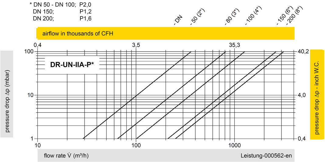
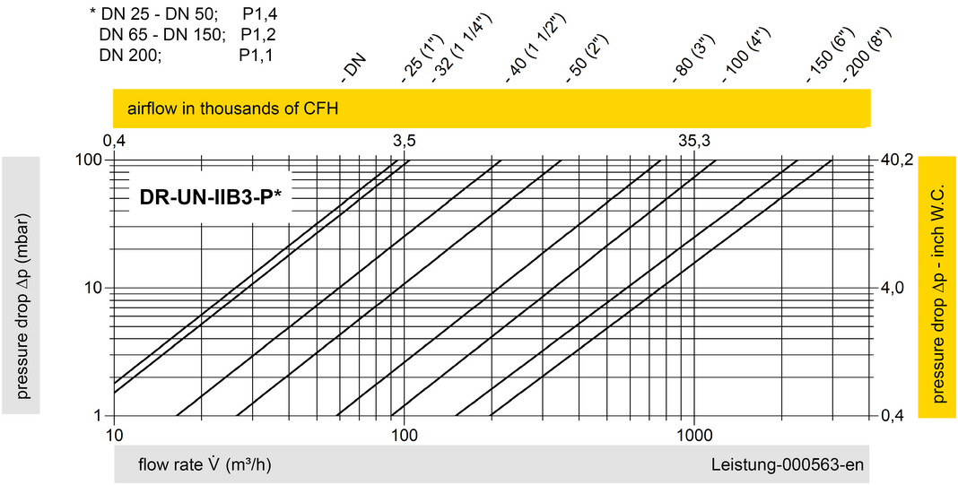
The flow capacity charts have been determined with a calibrated and TÜV certified flow capacity test rig. Volume flow V in (m³/h) and CFH refer to the standard reference conditions of air ISO 6358 (20°C, 1bar). For conversion to other densities and temperatures refer to Sec. 1: “Technical Fundamentals”.