UB/DF
Pressure Diaphragm Valve deflagration- and endurance burning-proof
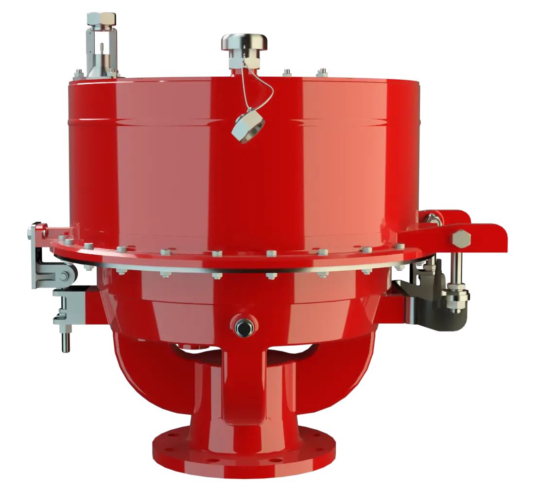
Features
Function and Description
Highly Developed Pressure Relief Valve
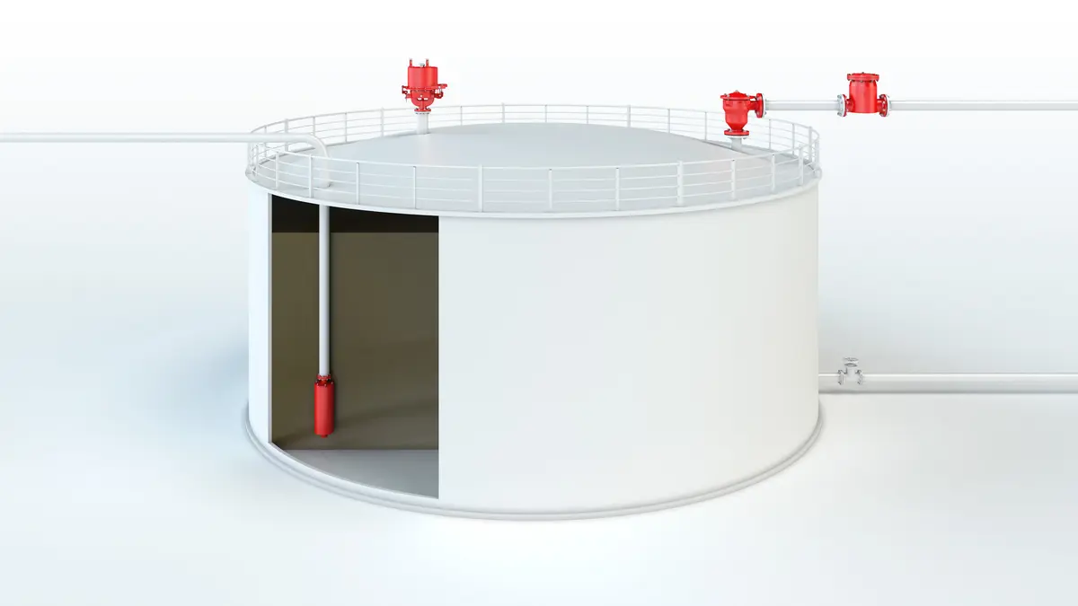
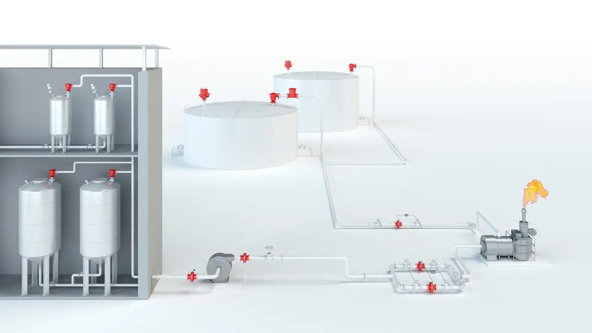
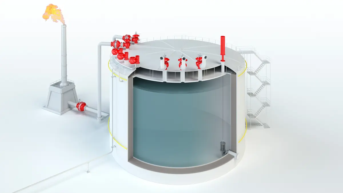
The PROTEGO® UB/DF diaphragm Diaphragm A diaphragm is a thin layer of material, which has a large surface area. valve is a worldwide unique deflagration Deflagration Explosion propagating at subsonic velocity. -proof and endurance burning Endurance burning Stabilized burning for an unlimited time. -proof pressure relief valve Pressure-relief valve Valve designed to open and relieve excess pressure and to reclose and prevent the further flow of fluid after normal conditions have been restored. combining the function of a dynamic and static Flame Arrester Flame arrester Device fitted to the opening of an enclosure, or to the connecting pipe work of a system of enclosures, and whose intended function is to allow flow but prevent the transmission of a flame. . It is primarily used as a device Device A device is a pipe component that influences the media flow by opening, closing, or partially shutting off the flow channel or by dividing or mixing the media flow. for flame transmission-proof Flame transmission-proof Characteristic of a device to avoid flashback. out-breathing on tanks, containers, and process equipment Equipment Machines, appliances, fixed or mobile devices, control parts and accessories, and warning and prevention systems, whether separate or combined, intended for the generation, transfer, storage, measurement, control, and conversion of energy, and for the processing of materials, which have their own potential source of ignition and may cause an explosion. . The valve offers reliable protection against overpressure Overpressure Overpressure refers to an increase in pressure in a system or vessel above the normal operating pressure. , prevents the in-breathing of air and product Product Includes equipment, protective systems, devices, components and combinations of these. losses almost up to the set pressure Set pressure Set pressure is the gauge pressure at the device inlet at which the relief device is set to start opening under service conditions. , and protects against atmospheric deflagration and endurance burning if stabilized burning Stabilized burning Steady burning of a flame stabilized at, or close to the flame arrester element. occurs.

For Explosion Group IIB3
The PROTEGO® UB/DF diaphragm valve has proven itself over many years under a wide variety of operating conditions in the mineral oil and chemical industries. The set pressure is adjusted with a freeze resistant water-glycol mixture which ensures safe operation under extreme cold weather conditions. The PROTEGO® UB/DF valve is available for substances from explosion Explosion Abrupt oxidation or decomposition reaction producing an increase in temperature, pressure, or in both simultaneously. group IIB3 (NEC group C MESG ≥ 0.65 mm).
Operation of the Overpressure Relief Valves
When the pressure Pressure (gauge pressure) Pressure for which the value is equal to the algebraic difference between the absolute pressure and the atmospheric pressure. in the tank reaches the set pressure, the diaphragm (1) on the outer valve seat Valve seat The valve seat is a component on which the valve pallet rests when the valve is closed. ring (2) is lifted and vapors are released into the environment. The set pressure is adjusted by the weight of the liquid load (water-glycol mixture) in the outer ring chamber (3). The overpressure chamber is equipped with an opening (4) to keep the pressure in balance. The opening is equipped with a FLAMEFILTER® to prevent flame transmission into the overpressure chamber. The overpressure setting is determined by the filling level of the loading liquid and can be adjusted by a floating level indicator (5).
Overpressure Protection with Advanced Sealing Technology
The tank pressure Tank pressure Tank pressure is the pressure within a tank. is maintained up to the set pressure with a tightness that is above the normal standards due to our highly developed manufacturing technology. This is achieved by the liquid loaded diaphragm pressing tightly around the special designed valve seat surface area even when the operating pressure Operating pressure Operating pressure is the pressure existing at normal operating conditions within the system being protected. increases, which reduces surface pressure and unnecessary leakage. After the overpressure is released, the valve re-seats and provides a tight seal Seal A seal prevents or limits unwanted transfer of product from one container to another. Seal is used as superordinate term for all types of sealing elements. .
Dynamic Flame Arresting at Overpressure Conditions
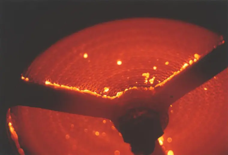
If the set pressure is exceeded, explosive gas/product vapor/air mixtures are released into the atmosphere. The speed at which these mixtures exit the annular gap between the diaphragm and the outer valve seat ring is considerably greater than the flame speed. If this mixture ignites, flashback Flashback Phenomenon occurring in a flammable mixture of air and gas when the local velocity of the combustible mixture becomes less than the flame velocity, causing the flame to travel back to the point of mixture. into the tank is prevented. If the mixture flow continues, the dynamic flame arresting feature prevents flashback, even in the case of endurance burning.
Main Component – PROTEGO® Flame Arrester Unit
Even at relatively low flow rates, e.g., during thermal out-breathing, the gap formed by the volumetric flow is so narrow, that flames in the gap are extinguished, and a flashback is prevented. At very low pressure settings, the explosion Explosion Abrupt oxidation or decomposition reaction producing an increase in temperature, pressure, or in both simultaneously. pressures resulting from an atmospheric deflagration may be strong enough to lift Lift Lift is the actual travel of the valve pallet from the main valve out of the closed position. the diaphragm off the valve seat rings. The ignition into the tank can be prevented by installing the PROTEGO® Flame Arrester Unit PROTEGO® flame arrester unit The PROTEGO® flame arrester unit is the main component of a flame arrester. It prevents flame propagation. (8). This PROTEGO® Flame Arrester Unit provides additional protection against atmospheric deflagration when the valve is open for maintenance Maintenance Combination of all technical and administrative actions, including supervision actions, intended to maintain or restore a unit in working order. and inspection.
Many Individual Certifications
The valve can be used at an operating temperature Operating temperature Temperature reached when the equipment is operating under design conditions. of up to +60°C/140°F and meets the requirements of European Tank Design Standard EN 14015 (Appendix L) and ISO 28300 (API 2000). EU conformity according to the currently valid ATEX directive. Approvals according to other national/international regulations on request.
Dimensions
To select the nominal size Nominal size The nominal size is an alphanumeric designation of size for components in a piping system, used for reference purposes, comprising the letters DN followed by a dimensionless integer that is indirectly related to the physical size of the bore or outside diameter of the connections, expessed in millimeters. (DN), please use the flow capacity charts on the following pages
| DN | pressure | pressure | 80 / 3" | pressure | pressure | 100 / 4" | pressure | pressure | 150 / 6" |
| a | up to +28 mbar | up to +11.2 inch W.C. | 615 / 24.21 | up to +28 mbar | up to +11.2 inch W.C. | 645 / 25.39 | up to +25 mbar | up to +10 inch W.C. | 680 / 26.77 |
| a | > +28 mbar | > +11.2 inch W.C. | 765 / 30.12 | > +28 mbar | > +11.2 inch W.C. | 795 / 31.30 | > +25 mbar | > +10 inch W.C. | 830 / 32.68 |
| b | 410 / 16.14 | 485 / 19.09 | 590 / 23.23 |
Dimensions in mm / inches
Pressure settings > +50 mbar / +20 inch W.C. (DN 80/3”), > +45 mbar / +18 inch W.C. (DN 100/4”), > +46 mbar / +18.4 inch W.C. (DN150/6”) with additional liquid reservoir - dimensions upon request
Dimensions for pressure diaphragm valves with heating coil Heating coil A heating coil is a pipe connection consisting of several pipe sections. upon request
Material selection for housing
| Design | B | C | D |
| Housing Housing A housing is a solid shell, which surrounds a content, either protecting the content from external influences, or protecting the environment from the content. | Cast Iron | Steel | Stainless Steel |
| Valve top | Stainless Steel | Stainless Steel | Stainless Steel |
| Heating coil (UB / DF-H-...) | Stainless Steel | Stainless Steel | Stainless Steel |
| Valve seat | Stainless Steel | Stainless Steel | Stainless Steel |
| Gasket | FPM | FPM | PTFE |
| Diaphragm | A, B | A, B | A, B |
| Flame arrester unit Flame arrester unit Flame arrester casing with FLAMEFILTER® set. | A | C | C |
Option: Housing with ECTFE- lining Lining Protective plastic lining with a defined minimum/maximum thickness to protect against aggressive mixtures (e.g., acid).
Special materials upon request
Material selection
| Design | A | B |
| Diaphragm | FPM | FEP |
Special materials upon request
Material combinations of flame arrester unit
| Design | A | C |
| FLAMEFILTER® cage | Cast Iron | Stainless Steel |
| FLAMEFILTER® | Stainless Steel | Stainless Steel |
| Spacer Spacer The spacer is a component that is generally used in a PROTEGO® flame arrester as a spacer within the FLAMEFILTER® set. | Stainless Steel | Stainless Steel |
Special materials upon request
Selection of explosion group
| MESG | Expl. Gr. (IEC / CEN) | Gas Group (NEC) |
| ≥ 0,65 mm | IIB3 | C |
Special approvals upon request
Flange connection type
| EN 1092-1; Form B1 |
| ASME B16.5 CL 150 R.F. |
other types upon request
Design Types and Specifications
The diaphragm is pressurized by liquid. Higher pressures can be achieved upon request with a special liquid reservoir.There are two different designs:
In addition to the standard design, a series of specially developed designs, which are particularly suitable for operating conditions to which these products are subjected, can be provided upon request (for example, for acrylics or styrene storage tanks, etc.).
Settings
| DN 80 | +3.5 mbar | +50 mbar |
| +1.4 inch W.C. | +20 inch W.C. | |
| DN 100 | +3.5 mbar | +45 mbar |
| +1.4 inch W.C. | +18 inch W.C. | |
| DN 150 | +3.5 mbar | +46 mbar |
| +1.4 inch W.C. | +18.4 inch W.C. |
Higher pressure settings up to +140 mbar (56.2 inch W.C.) in special design with additional liquid reservoir as well as lower pressure settings upon request.
Flow Capacity Chart
UB/DF DN80 Pressure
UB/DF DN100 Pressure
UB/DF DN150 Pressure
The flow capacity charts have been determined with a calibrated and TÜV certified flow capacity test rig. Volume flow V in (m³/h) and CFH refer to the standard reference conditions of air ISO 6358 (20°C, 1bar). For conversion to other densities and temperatures refer to Sec. 1: “Technical Fundamentals”.