PM-HF
Pressure/Vacuum Relief Valve Pilot-operated diaphragm valve

Features
Function and Description
Combined Pressure and Vacuum Relief Valve
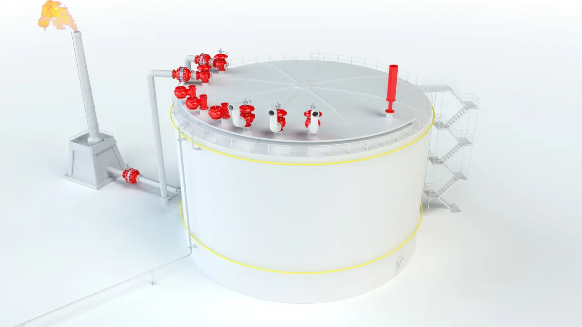
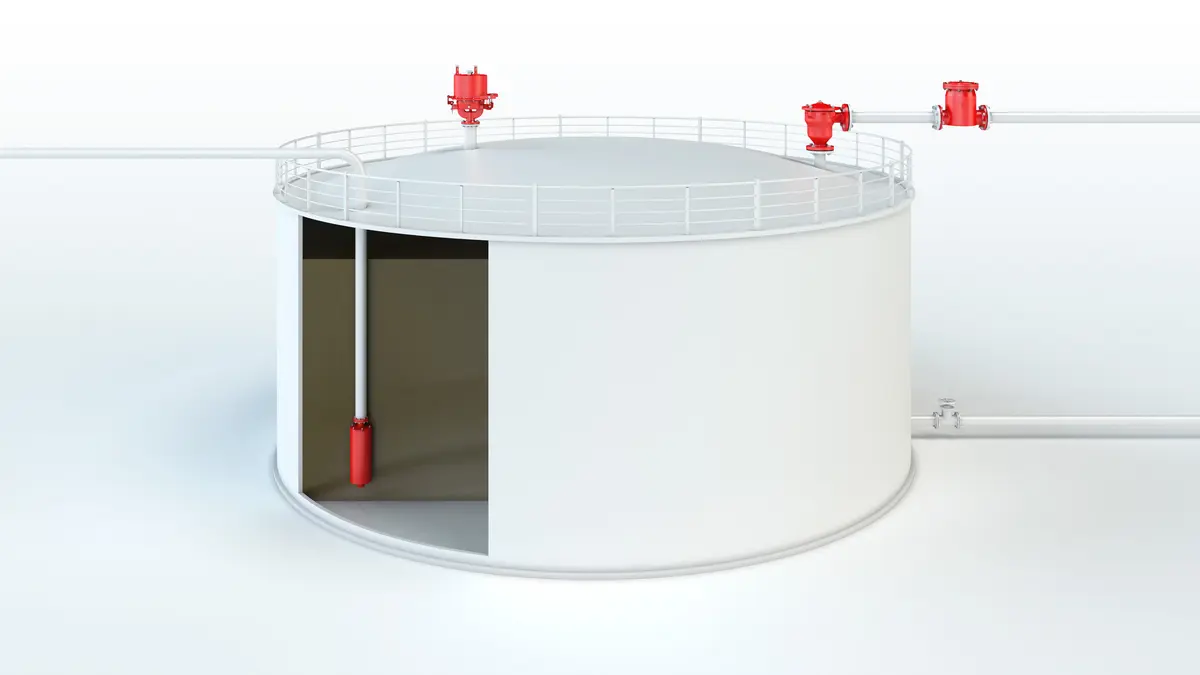
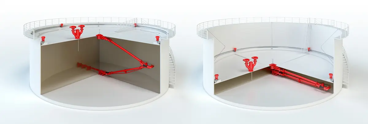
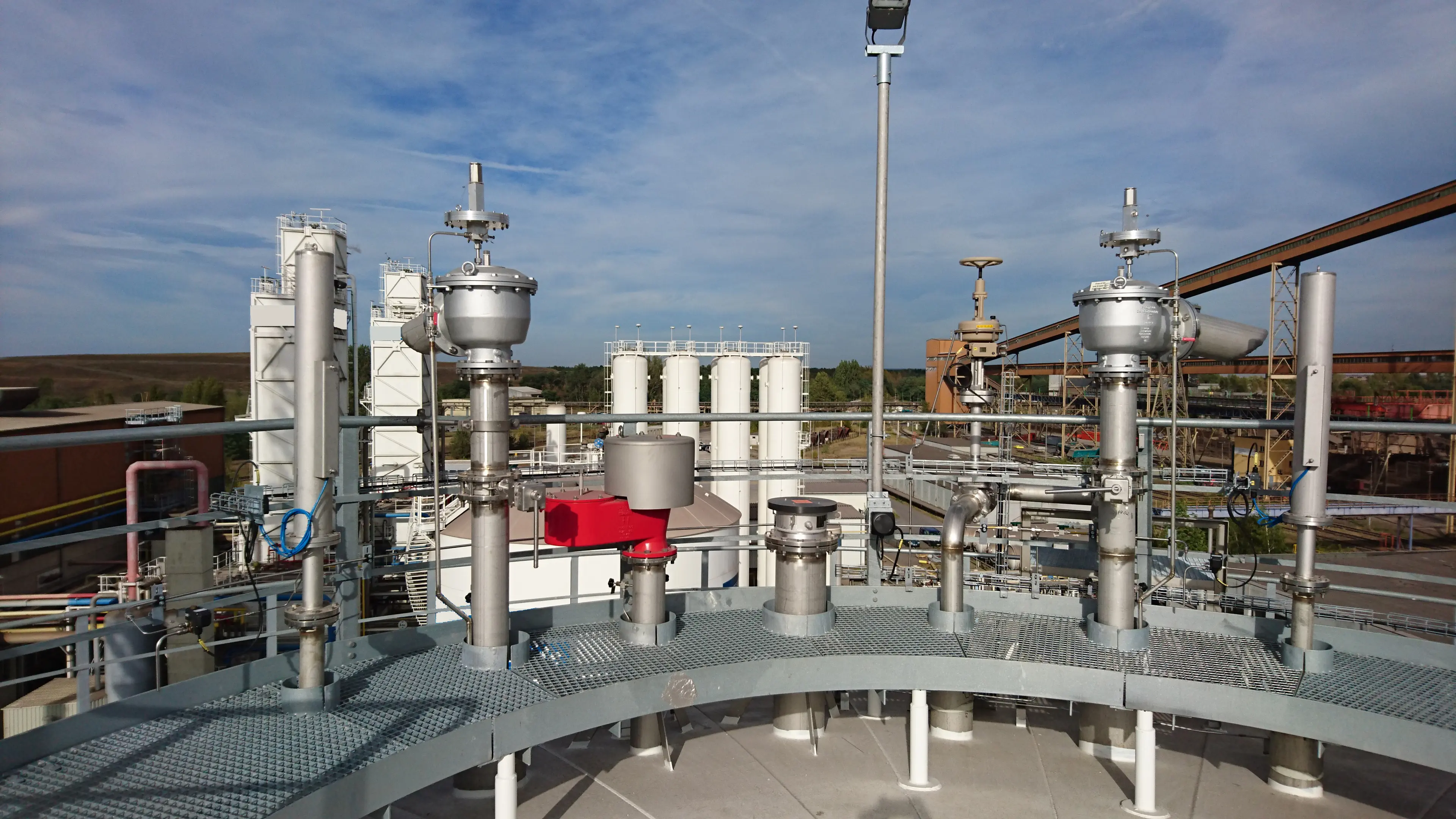
The PROTEGO® Type PM-HF pilot-controlled diaphragm Diaphragm A diaphragm is a thin layer of material, which has a large surface area. valve is a highly developed valve for pressure Pressure (gauge pressure) Pressure for which the value is equal to the algebraic difference between the absolute pressure and the atmospheric pressure. and vacuum Vacuum Vacuum is the pressure in an enclosed space that is lower than the ambient pressure. relief. Primarily used as a device Device A device is a pipe component that influences the media flow by opening, closing, or partially shutting off the flow channel or by dividing or mixing the media flow. for outbreathing in tanks, vessels, and process engineering equipment Equipment Machines, appliances, fixed or mobile devices, control parts and accessories, and warning and prevention systems, whether separate or combined, intended for the generation, transfer, storage, measurement, control, and conversion of energy, and for the processing of materials, which have their own potential source of ignition and may cause an explosion. it also offers reliable protection from vacuum and overpressure Overpressure Overpressure refers to an increase in pressure in a system or vessel above the normal operating pressure. . It prevents intake of air and unacceptable product Product Includes equipment, protective systems, devices, components and combinations of these. vapor loss up to and until the set-to-operate pressure is reached. The valve can be used as an inbreathing device as well. In such an application, the main valve is directly controlled when exposed to a vacuum, i.e. it functions as a weight-loaded diaphragm valve.
Tank Pressure Controls the Pilot Valve
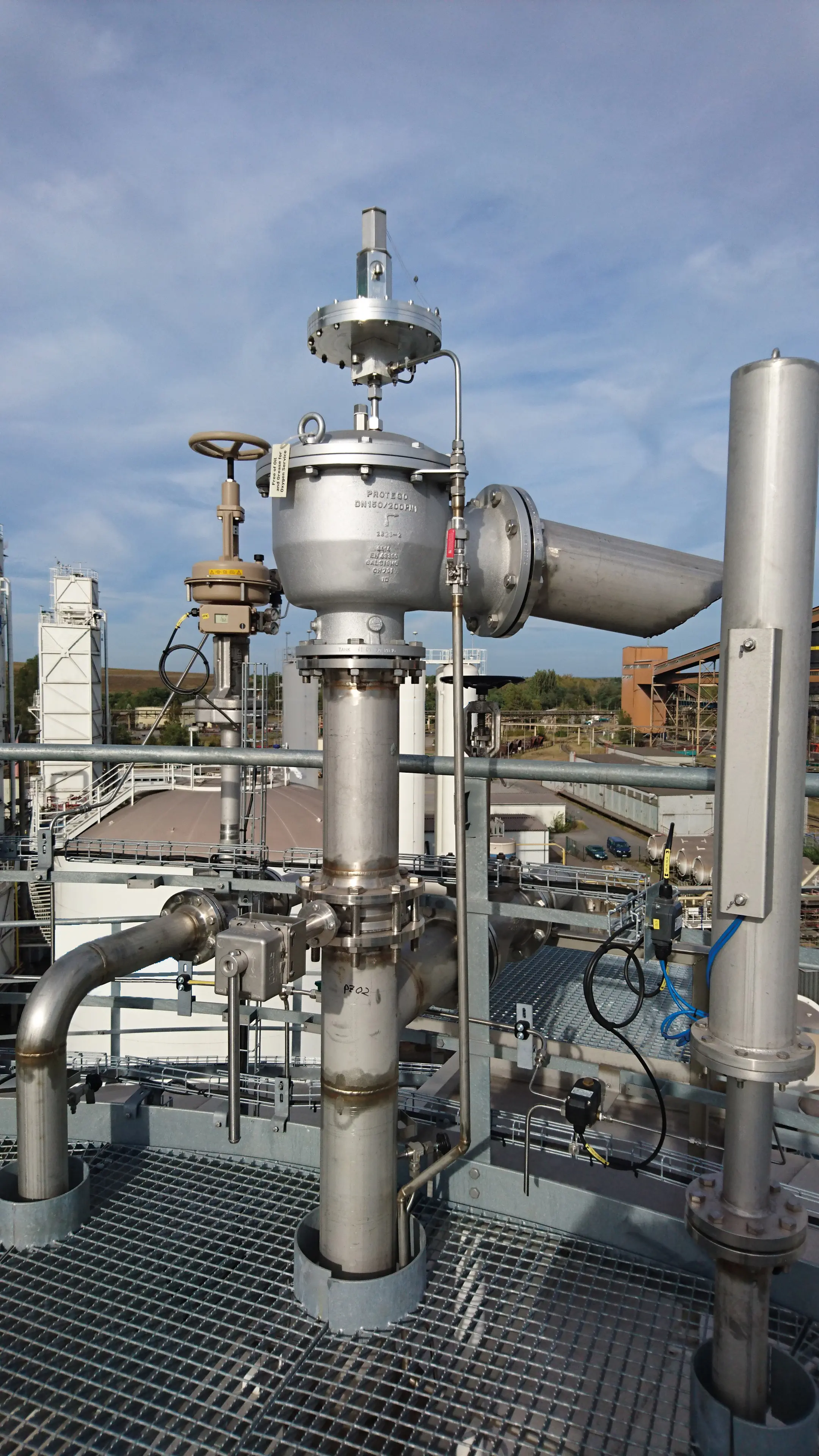
The main valve is controlled by a pilot valve Pilot valve The pilot valve is an assembly of a pilot operated valve, which is mounted on the main valve and is used to control the main valve. . The latter in turn is controlled by the tank pressure Tank pressure Tank pressure is the pressure within a tank. . A small amount fluid stored in the tank released into the atmosphere by the pilot when the valve opens. The set-to-operate pressure is adjusted on the pilot valve by increasing or decreasing (as appropriate) the tension of a spring Spring A spring is a spiral of wire which returns to its original shape after it is pressed or pulled. .
Extreme Tightness
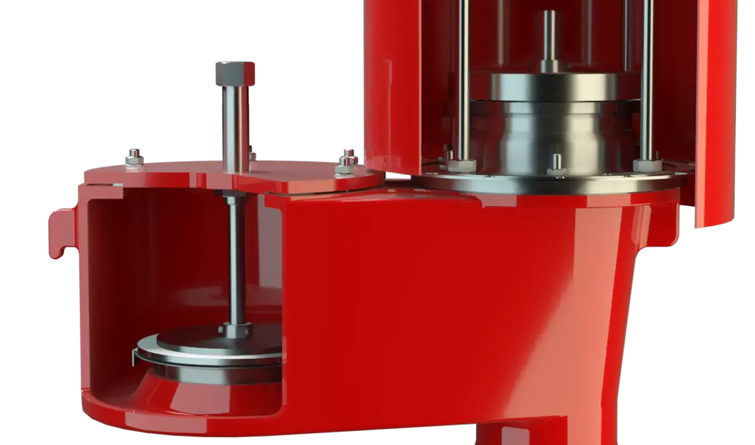
As the working pressure rises, the closing force acting on the main valve increases, i.e. the valve's tight-sealing is enhanced until the set-to-operate pressure is reached, thus preventing leakage. Once the valve has commenced to lift Lift Lift is the actual travel of the valve pallet from the main valve out of the closed position. it opens fully within a 10% pressure rise or the opening pressure difference and the nominal volumetric fl ow is discharged through a fully open valve. If and when this level is exceeded the pressure increase will follow the performance curve (Δp/V.curve). From set pressure Set pressure Set pressure is the gauge pressure at the device inlet at which the relief device is set to start opening under service conditions. to full capacity (fully open valve) the pressure increase is 100% in case of vacuum venting/inbreathing function.
Advanced Manufacturing Technology
Due to the sophisticated manufacturing technology, the tank pressure is maintained up to the set-to-operate pressure, with seal Seal A seal prevents or limits unwanted transfer of product from one container to another. Seal is used as superordinate term for all types of sealing elements. -tight requirements far above common standards being met. This feature is achieved through valve seats made of high-grade stainless steel with precisely ground valve pallets. Once the excess pressure is relieved or pressure below atmospheric balanced out, the valve reseats and seals tight again.
Dimensions
To select the nominal size Nominal size The nominal size is an alphanumeric designation of size for components in a piping system, used for reference purposes, comprising the letters DN followed by a dimensionless integer that is indirectly related to the physical size of the bore or outside diameter of the connections, expessed in millimeters. (DN), use the flow capacity charts on the following pages
| DN1 | 80 / 3" | 100 / 4" | 150 / 6" | 200 / 8" | 250 / 10" | 300 / 12" | 300 / 12" |
| DN2 | 100 / 4" | 150 / 6" | 200 / 8" | 250 / 10" | 300 / 12" | 350 / 14" | 400 / 16" |
| a | 225 / 8.86 | 250 / 9.87 | 325 / 12.80 | 375 / 14.76 | 450 / 17.72 | 500 / 19.69 | 500 / 19.69 |
| b | 150 / 5.91 | 175 / 6.89 | 225 / 8.86 | 250 / 9.84 | 270 / 10.63 | 300 / 12.81 | 325 / 12.80 |
| c | 275 / 10.83 | 330 / 12.99 | 445 / 17.52 | 550 / 21.65 | 665 / 26.18 | 785 / 30.91 | 785 / 30.91 |
| d | 376 / 14.80 | 429 / 16.89 | 536 / 21.10 | 607 / 23.90 | 678 / 26.69 | 796 / 31.34 | 846 / 33.31 |
| e | 763 / 30.04 | 770 / 30.31 | 923 / 36.34 | 977 / 38.46 | 1052 / 41.42 | 1173 / 46.18 | 1223 / 48.15 |
| f | 35 / 1.38 | 40 / 1.57 | 40 / 1.57 | 50 / 1.97 | 50 / 1.97 | 50 / 1.97 | 50 / 1.97 |
Dimensions in mm / inches
Material selection for housing
| Design | A | B |
| Housing Housing A housing is a solid shell, which surrounds a content, either protecting the content from external influences, or protecting the environment from the content. | Aluminium | Stainless Steel |
| Valve seat Valve seat The valve seat is a component on which the valve pallet rests when the valve is closed. | Stainless Steel | Stainless Steel |
| Sealing | KL-C-4106 | KL-C-4106 |
| Main diaphragm protection | Stainless Steel | Stainless Steel |
| Pilot lines | Stainless Steel | Stainless Steel |
| Pilot housing | Aluminium | Aluminium / Stainless Steel |
| Pilot diaphragm | FEP | FEP |
Special materials upon request
Coefficient of Discharge
| DN1 | 80 / 3" | 100 / 4" | 150 / 6" | 200 / 8" | 250 / 10" | 300 / 12" | 300 / 12" |
| DN2 | 100 / 4" | 150 / 6" | 200 / 8" | 250 / 10" | 300 / 12" | 350 / 14" | 400 / 16" |
| do | 81 / 3.19 | 107 / 4.21 | 160 / 6.30 | 208 / 8.19 | 260 / 10.24 | 310 / 12.20 | 310 / 12.20 |
| K | 0,68 | 0,68 | 0,63 | 0,59 | 0,58 | 0,54 | 0,61 |
DN1 = Size Inlet
DN2 = Size Outlet
d0 = Orifice Diameter (mm / inches)
K = Coefficient of Discharge
Flange connection type
| EN 1092-1; Form B1 |
| ASME B16.5 CL 150 R.F. |
other types upon request
Design Types and Specifications
Following designs are available:Additional special devices available upon request
*It is recommended thet an external control line be provided with direct connection to the tank
Settings
| Pressure: | +10 mbar | +1034 mbar |
| +4 inch W.C. | +413.6 inch W.C. | |
| Vacuum: | -3.0 mbar | -7 mbar |
| -1.2 inch W.C. | -2.8 inch W.C. | |
| -2.2 mbar | -7 mbar | |
| -0.88 inch W.C. | -2.8 inch W.C. |
Higher or lower settings upon request.
Flow Capacity Chart
The flow capacity charts have been determined with a calibrated and TÜV certified flow capacity test rig. Volume flow V in (m³/h) and CFH refer to the standard reference conditions of air ISO 6358 (20°C, 1bar). For conversion to other densities and temperatures refer to Sec. 1: “Technical Fundamentals”.