Features
Function and Description
High-Performance Air Drying Units for Storage Tanks
PROTEGO® Air-Drying Device Device A device is a pipe component that influences the media flow by opening, closing, or partially shutting off the flow channel or by dividing or mixing the media flow. of Types LA or LA/V is used when suction air must be dried for atmospheric venting of storage tanks where only little or no humidity is allowed to get into the tank or the stored product Product Includes equipment, protective systems, devices, components and combinations of these. due to the process engineering. They are usually used in vertical or horizontal aboveground tanks which store non-flammable or flammable liquids, and which must not be vented with humid air for safe operation.
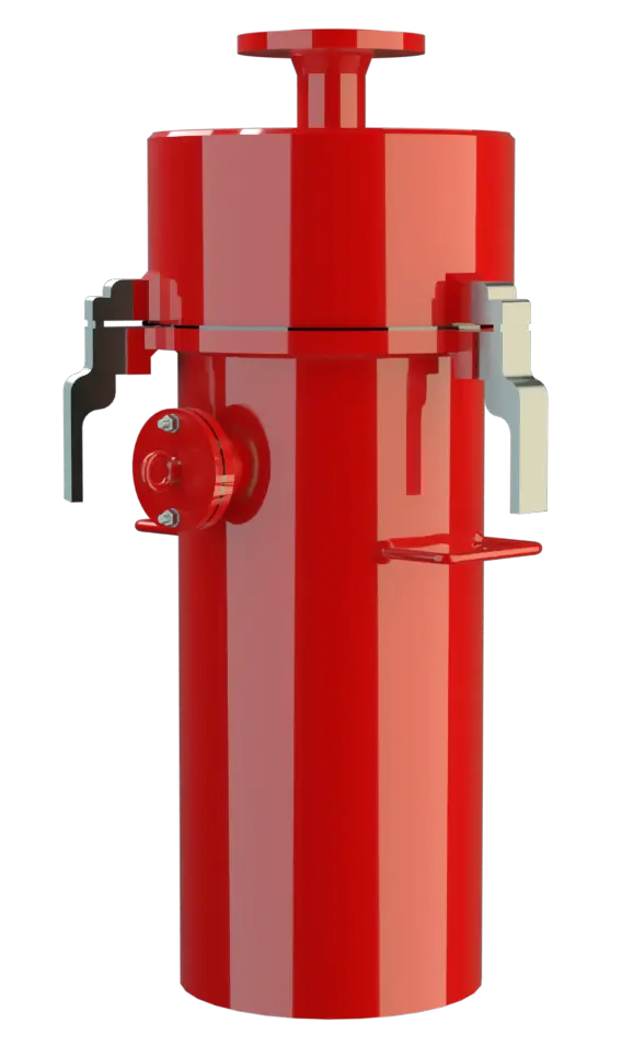
The single device PROTEGO® LA mainly consists of the drying agent container (1). Its snap closing elements (2) connect it to the connection head (3) with flange connection according to DIN 2501 or to any other international standard. The bottom screen (4) and the protective strainer (5) are firmly welded into the drying agent container (1). The upper strainer cover (6) is loose. It can be removed easily to add or remove the drying agent. The connection head (3) contains the sealing plate (7) that closes the connection head opening when taking the drying agent container off. No humid air can be sucked in when changing the drying agent container.
The upper part of the drying agent container (1) holds the integrated control cartridge (8). The control cartridge can be removed during operation. It shows if the drying agent contains humidity and has to be replaced for regeneration. Depending on the required flow rates or prescribed pressure Pressure (gauge pressure) Pressure for which the value is equal to the algebraic difference between the absolute pressure and the atmospheric pressure. losses the drying agent containers are delivered in two sizes – type I or type II. As parts of a modular system they are assembled into larger performance units.
Effective Air Drying with KC® Drying Beads
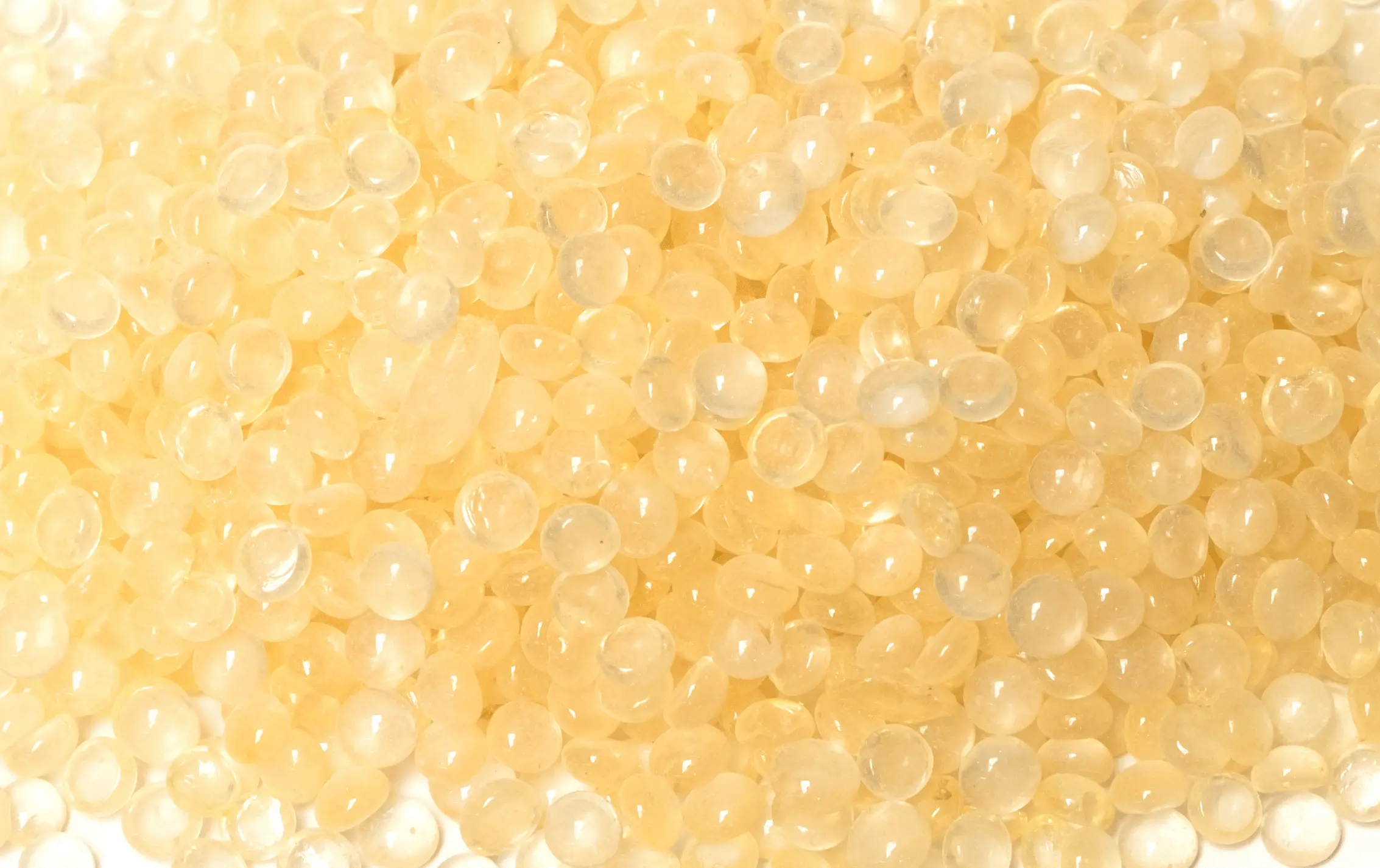
KC® drying pearls are used as the drying agent. The control cartridge (figure 1) is filled with special KC® indicator drying pearls. The required filling levels are specified in the relevant operating instructions. The air-drying device Air drying apparatus An air drying apparatus is used for drying inlet air on atmospheric tank ventilation systems type LA/V is essentially similar to type LA. Additionally, it has a replaceable check valve Check valve A check valve allows flow of the operating media in one direction and prevents flow in the opposite direction. (9) with protective strainer and valve pallet Valve pallet Valve pallet is the generic term for the assembly that rests on the valve seat. (10) integrated in the inlet connection. When no air is sucked in through the air-drying device the device is sealed and tight towards the atmosphere. So at high air humidity the drying agent in the lower area of the drying agent container cannot absorb moisture.
Integrated Air Drying Solutions for Tank Venting Systems
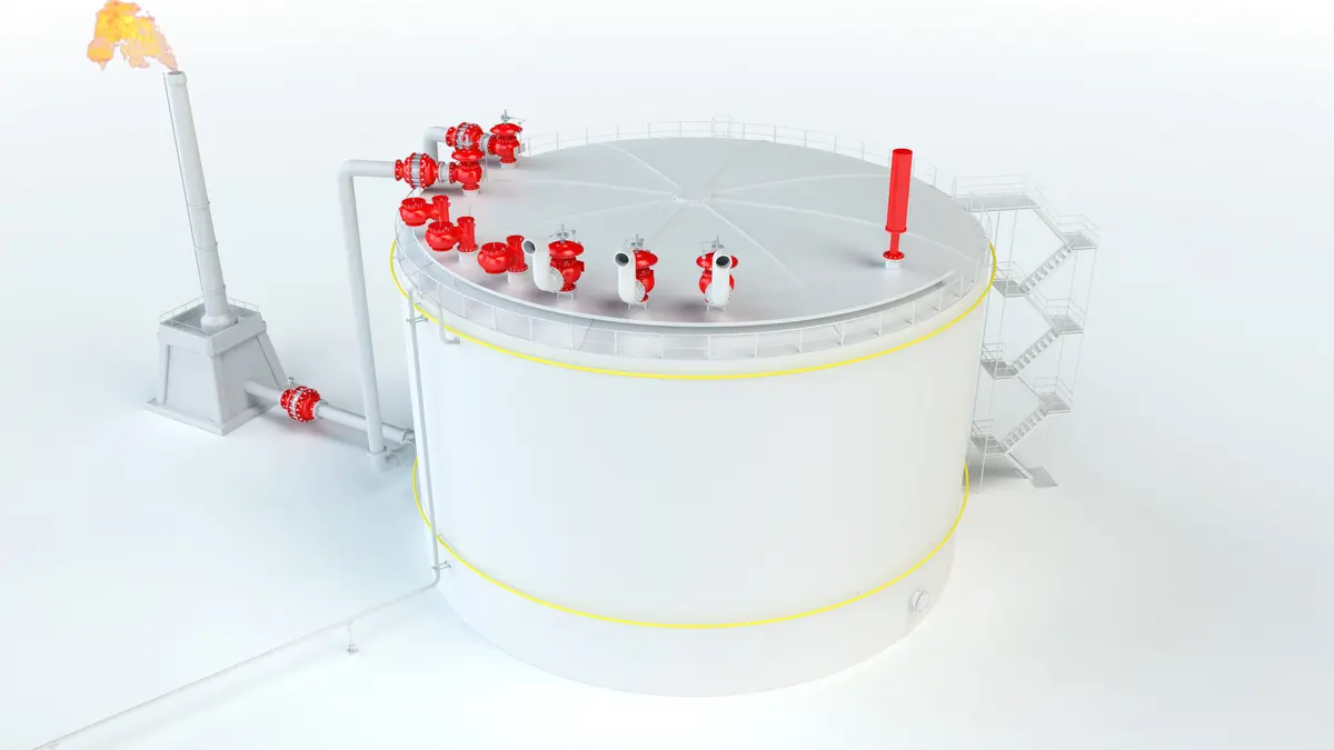
The FEP diaphragm Diaphragm A diaphragm is a thin layer of material, which has a large surface area. with air cushion sealing (figure 2) is used as valve pallet sealing up to pressure range II. From pressure range III, a lapped metallic sealing is used (figure 3). Air-drying devices of types LA or LA/V may be integrated into complete tank venting systems (see figures 4 and 5). If flammable liquids are stored in the tank, then Flame Arresters Flame arrester Device fitted to the opening of an enclosure, or to the connecting pipe work of a system of enclosures, and whose intended function is to allow flow but prevent the transmission of a flame. have to be installed in addition to the air-drying device and the pressure and vacuum Vacuum Vacuum is the pressure in an enclosed space that is lower than the ambient pressure. relief valves. Depending on the operating conditions it is also possible to combine other vent valves with the integrated air-drying device.
Monitoring and Replacement of Desiccant in the Air Drying Unit
When the set vacuum Set vacuum Internal negative gauge pressure at which a vacuum valve first opens. is reached in the tank, the vacuum relief valve Vacuum relief valve A vacuum relief valve is used to ventilate a part of the system and protects it from impermissible underpressure. – for instance PROTEGO® type DZ/T or DV/ZU on figures 4 and 5 – connected to the air-drying device opens and the drying device LA sucks in atmospheric air while the drying agent (KC® drying pearls) absorbs the atmospheric humidity. The drying agent must be replaced and regenerated when depleted. Using a control cartridge, it is easily possible to determine whether the drying agent is saturated with humidity.
Overpressure Control and Venting in Tank Ventilation Systems
If the specified pressure is reached in the examples shown in figures 4 or 5 the pressure side of the combined pressure and vacuum relief valve Pressure and vacuum relief valve A pressure and vacuum relief valve is a pressure equalization valve for impermissible pressure and vacuum in a closed system. opens and the product vapour/air mixture escapes into the atmosphere. The valve could be for instance PROTEGO® Type VD/SV or DV/ZU. Alternatively it is possible to pass the product vapour/air mixture through a suitable valve – e.g. PROTEGO® Type DV/ZU into an exhaust line or exhaust system. Under pressure the vacuum side of the above valves remains closed and the product vapours cannot pass into the drying agent.
Combined Pressure and Vacuum Relief Valve
In larger tanks it is recommended to also use combined pressure and vacuum relief valves e.g. PROTEGO® Type VD/SV. This ensures that in an emergency (failure of air-drying device) atmospheric air can be sucked in directly through the vacuum side. Often direct atmospheric emergency venting is required yet it is neither possible nor necessary to size the air-drying device for the maximum volume flow calculated (pump flow-rate and thermal flow according to EN 14015 or API 2000). Maximum thermal flow occurs only rarely and it is therefore usually sufficient to size the air-drying device according to the pump flow-rate for emptying and a thermal flow portion of approximately 25%.
Air Drying Unit with Integrated Vacuum Relief Valve
Essentially, the Air-Drying Device of Types PROTEGO® LA/V functions like type PROTEGO® LA. However, a check valve allows inbreathing only when the entire venting system Venting system System which consists of pipeline and devices for free out-breathing and in-breathing of plant components. – the tank and the drying container – is under vacuum at the set pressure Set pressure Set pressure is the gauge pressure at the device inlet at which the relief device is set to start opening under service conditions. of the check valve. The devices are designed for venting rates sufficient for the breathing of storage tanks. However, they do not replace any valves designed for emergency venting.
Monitoring and Combination of Air Drying Units
The drying agent saturation can be easily monitored using a control cartridge. The drying agent can be regenerated. Drying agent and control drying pearls are not included in the PROTEGO® LA or LA/V and can optionally be ordered together with the device. Figure 6 shows the combination options of PROTEGO® LA/V air-drying device in complete units. The overall dimensions, filling volumes and filling weights are also given in this figure.
Material selection Typ LA
| Design | A | B | |
| Housing Housing A housing is a solid shell, which surrounds a content, either protecting the content from external influences, or protecting the environment from the content. | Steel | Stainless Steel | |
| Bottom screen | Stainless Steel | Stainless Steel | |
| Protective strainer | Stainless Steel | Stainless Steel | |
| Cover | Steel | Stainless Steel |
Material selection Typ LA/V
| Design | A | B |
| Housing | Steel | Stainless Steel |
| Bottom screen | Steel | Stainless Steel |
| Protective strainer | Stainless Steel | Stainless Steel |
| Cover | Steel | Stainless Steel |
| Valve insert | Stainless Steel | Stainless Steel |
Material selection for vacuum relief valve
| Design | A | B | C |
| Vacuum range [mbar] [inch W.C.] | -3.5 up to -5.0 -1.4 up to -2.0 | ≥-5.0 up to -14 ≥-1.4 up to -5.6 | ≥-14 up to -35 ≥-5.6 up to -14 |
| Valve pallet | Aluminium | Stainless Steel | Stainless Steel |
| Sealing | FEP | FEP | Metal to Metal |
Data Necessary for Specification
Maximum allowable tank vacuum pT (mbar or Inch W.C.)Maximum possible volume flow V (m3/h or CFH) (when emptying the tank)
Pressure loss or Pipeline length
Tank material
Flange connection type
The connection flange is to EN 1092-1 or DIN 2501, PN 16. Optionally, the connecting flange can be made according to any international flange standard.Selection and Design
In a system shown in figure 4 the maximum vacuum in the tank is calculated depending on the volume flow of the pressure loss ∆pLA of the air drying-device LA and the opening pressure pO of the vent valve DZ/T or DV/ZU or the tank pressure Tank pressure Tank pressure is the pressure within a tank. pT given in the relevant capacity chart.
In a system according to figure 5 the maximum vacuum in the tank is calculated depending on the volume flow of the pressure loss ∆pLA of the air-drying device LA - plus check valve set pressure pVR - and opening pressure pO of the vent vent valve DZ/T or DV/ZU or the tank pressure pT given in the relevant capacity chart.
Additionally, the pressure loss in the pipeline between air-drying device and vent valve has to be taken into account; however, usually it is negligible.
Design Types and Specifications
There are two designs available:Flow Capacity Chart
The stated capacities are valid for the single device PROTEGO® LA and refer to the filling material KC® dryer pearls of 2 up to 5 mm Diameter. The totel pressure drop of typ PROTEGO® LA/V is ∆pLA/V results from the differential pressure ∆pLA/V plus adjusted Setting of vacuum valve pVR.