DR/SBW
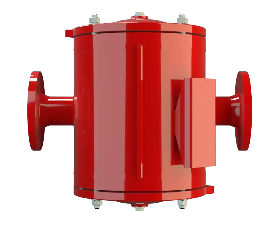
In-Line Detonation Flame Arrester for stable detonations and deflagrations in a straight through design with shock absorber, bidirectional
Features
Function and Description
Maintenance-Friendly In-Line-Detonation Flame Arrester
In the development of the PROTEGO® DR/SBW In-Line Detonation Detonation Explosion propagating at supersonic velocity and characterized by a shock wave. Flame Arrester Flame arrester Device fitted to the opening of an enclosure, or to the connecting pipe work of a system of enclosures, and whose intended function is to allow flow but prevent the transmission of a flame. , special effort was made to ease future maintenance Maintenance Combination of all technical and administrative actions, including supervision actions, intended to maintain or restore a unit in working order. of the Flame Arresters. The PROTEGO® Flame Arrester Unit PROTEGO® flame arrester unit The PROTEGO® flame arrester unit is the main component of a flame arrester. It prevents flame propagation. (5) can be removed and cleaned within moments without having to disassemble the piping. The effective shock absorber Shock absorber A shock absorber is a device that reduces the kinetic energy of a detonation. of the device Device A device is a pipe component that influences the media flow by opening, closing, or partially shutting off the flow channel or by dividing or mixing the media flow. and elaborate housing Housing A housing is a solid shell, which surrounds a content, either protecting the content from external influences, or protecting the environment from the content. geometry reduces the number of FLAMEFILTER® discs to a minimum.

Main Component – PROTEGO® Flame Arrester Unit
The device is symmetrical and offers bidirectional flame arresting protecting from stable detonations and deflagrations. The Flame Arrester consists of a double-jacket housing (1) with two integrated shock absorbers (2) with the PROTEGO® Flame Arrester Unit in the center. The PROTEGO® Flame Arrester Unit consists of several FLAMEFILTER® discs (4) and spacers firmly held in a FLAMEFILTER® cage FLAMEFILTER® cage The FLAMEFILTER® cage is a housing for a FLAMEFILTER® set. (3). The number of FLAMEFILTER® discs and their gap size depends on the arrester‘s conditions of use. By indicating the operating parameters such as the temperature, pressure Pressure (gauge pressure) Pressure for which the value is equal to the algebraic difference between the absolute pressure and the atmospheric pressure. and explosion Explosion Abrupt oxidation or decomposition reaction producing an increase in temperature, pressure, or in both simultaneously. group and the composition of the fluid, the optimum In-Line Detonation Flame Arrester can be selected. The PROTEGO® DR/SBW Series of Flame Arresters is available for explosion Explosion Abrupt oxidation or decomposition reaction producing an increase in temperature, pressure, or in both simultaneously. groups IIA to IIB3 (NFPA group D to C MESG ≥ 0.65 mm).

Many Individual Certifications
The standard design is approved at an operating temperature Operating temperature Temperature reached when the equipment is operating under design conditions. up to +60°C / 140°F and an absolute operating pressure Operating pressure Operating pressure is the pressure existing at normal operating conditions within the system being protected. acc. to table 3. Devices with special approvals can be obtained for higher pressures and higher temperatures upon request. Type-approved in accordance with the current ATEX Directive and as well as other international standards.
Dimensions
To select the nominal size Nominal size The nominal size is an alphanumeric designation of size for components in a piping system, used for reference purposes, comprising the letters DN followed by a dimensionless integer that is indirectly related to the physical size of the bore or outside diameter of the connections, expessed in millimeters. (DN) and nominal width (NG), please use the flow capacity charts on the following pages
| DN | 50 / 2" | 80 / 3" | 100 / 4" | 150 / 6" | 200 / 8" | 250 / 10" | 300 / 12" | 350 / 14" | 400 / 16" |
| NG | 150 / 6" | 150 / 6" | 200 / 8" | 300 / 12" | 500 / 20" | 500 / 20" | 600 / 24" | 700 / 28" | 800 / 32" |
| a | 225 / 8.86 | 225 / 8.86 | 275 / 10.83 | 350 / 13.78 | 550 / 21.65 | 550 / 21.65 | 725 / 28.54 | 800 / 31.50 | 825 / 32.48 |
| b | 210 / 8.27 | 210 / 8.27 | 220 / 8.66 | 290 / 11.42 | 525 / 20.67 | 525 / 20.67 | 590 / 23.23 | 655 / 25.78 | 725 / 28.54 |
| b1* | 325 / 12.80 | 325 / 12.80 | 360 / 14.17 | 475 / 18.70 | 835 / 32.87 | 835 / 32.87 | 960 / 37.80 | 1075 / 42.32 | 1215 / 47.83 |
| c | 395 / 15.55 | 395 / 15.55 | 410 / 16.14 | 475 / 18.70 | 630 / 24.80 | 630 / 24.80 | 700 / 27.56 | 765 / 30.12 | 835 / 32.87 |
| c1* | 450 / 17.72 | 450 / 17.72 | 465 / 18.31 | 530 / 20.87 | 730 / 28.74 | 730 / 28.74 | 800 / 31.50 | 865 / 34.06 | 935 / 36.81 |
| d | 275 / 10.83 | 275 / 10.83 | 325 / 12.80 | 460 / 18.11 | 840 / 33.07 | 840 / 33.07 | 1000 / 39.37 | 1150 / 45.28 | 1250 / 49.21 |
Dimensions in mm / inches
* b1 dismantling dimension for servicing
c1 dismantling dimension for servicing (
temperature sensor
Temperature sensor
Temperature sensor for monitoring the temperature.
)
Material selection for housing
| Design | A | B | C |
| Housing | Steel | Stainless Steel | Hastelloy |
| Heating jacket (DR / SBW-H-(T)-...) | Steel | Stainless Steel | Stainless Steel |
| Cover with shock absorber | Steel | Stainless Steel | Hastelloy |
| Gasket | FPM* | PTFE | PTFE |
| Flame arrester unit Flame arrester unit Flame arrester casing with FLAMEFILTER® set. | A | C, D | E |
* for devices exposed to elevated temperatures above 150°C / 302 °F (T150), gaskets made of PTFE. Special device with unidirectional shock absorber DR/SW-... from DN 50 resp. NG 150 available.
Special materials upon request
Material combinations of flame arrester unit
| Design | A | C | D | E |
| FLAMEFILTER® cage | Steel | Stainless Steel | Stainless Steel | Hastelloy |
| FLAMEFILTER®* | Stainless Steel | Stainless Steel | Hastelloy | Hastelloy |
| Spacer Spacer The spacer is a component that is generally used in a PROTEGO® flame arrester as a spacer within the FLAMEFILTER® set. | Stainless Steel | Stainless Steel | Hastelloy | Hastelloy |
* the FLAMEFILTER® are also available in the materials Tantalum, Inconel, Copper, etc. when the listed housing and cage materials are used.
Special materials upon request
Selection of explosion group
| MESG | Expl. Gr. (IEC / CEN) | Gas Group (NEC) |
| > 0,90 mm | IIA | D |
| ≥ 0,65 mm | IIB3 | C |
Special approvals upon request
Selection of max. operating pressure
| DN | 50 / 2" | 80 / 3" | 100 / 4" | 150 / 6" | 200 / 8" | 250 / 10" | 300 / 12" | 350 / 14" | 400 / 16" | ||
| NG | 150 / 6" | 150 / 6" | 200 / 8" | 300 / 12" | 500 / 20" | 500 / 20" | 600 / 24" | 700 / 28" | 800 / 32" | ||
| Expl. Gr. | IIA | Pmax | 4 / 58 | 4 / 58 | 3 / 43.5 | 3 / 43.5 | 1.6 / 23.2 | 1.6 / 23.2 | 1.1 / 15.9 | 1.1 / 15.9 | 1.1 / 15.9 |
| Expl. Gr. | IIB3 | Pmax | 1.7 / 24.6 | 1.7 / 24.6 | 1.7 / 24.6 | 1.7 / 24.6 | 1.2 / 17.4 | 1.2 / 17.4 | 1.1 / 15.9 | 1.1 / 15.9 | 1.1 / 15.9 |
Pmax = Maximum allowable operating pressure in bar / psi absolut, higher operating pressure upon request
Specification of max. operating temperature
| ≤ 60°C / 140°F | Tmaximum allowable operating temperature in °C |
| - | Designation |
higher operating temperatures upon request
Flange connection type
| EN 1092-1; Form B1 |
| ASME B16.5 CL 150 R.F. |
other connections upon request
Design Types and Specifications
There are four different designs available:Additional special flame arresters upon request
*Resistance thermometer for device group II, category (1) 2 (GII cat. (1) 2)
Flow Capacity Chart
The flow capacity charts have been determined with a calibrated and TÜV certified flow capacity test rig. Volume flow V in (m³/h) and CFH refer to the standard reference conditions of air ISO 6358 (20°C, 1bar). For conversion to other densities and temperatures refer to Sec. 1: “Technical Fundamentals”.