Características
Función y descripción
Highly Developed Pressure Relief Valve
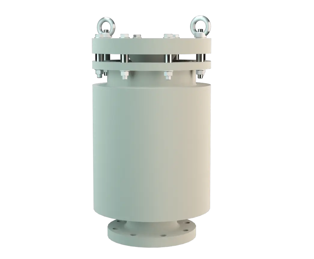
The PROTEGO® Valve D/KSM is a state-of-the-art pressure relief valve with excellent flow performance made out of high grade synthetic material. It is primarily used as a safety fitting for relieving pressure in tanks, containers, and process engineering equipment. The valve prevents emission losses almost up to the set pressure. The valve is a perfect solution for corrosive, polymerizing, or sticky substances. The device will start to open as soon as the set pressure is reached and only required 10% overpressure to reach full lift.
Full Lift Technology
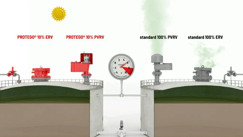
Continuous investments in and a commitment to research and development have allowed PROTEGO® to develop a low pressure valve which has the same opening characteristic as a high pressure safety relief valve. This “Full Lift Type” technology allows the valve to be set at just 10% below the maximum allowable working pressure ( MAWP Maximal erlaubter Betriebsdruck (MAWP) Maximaler zulässiger Überdruck im oberen Bereich eines kompletten Behälters in normaler Betriebsstellung bei der genannten übereinstimmenden Temperatur, die für diesen Druck spezifiziert ist. ) of the tank and still safely vent the required mass flow.
Advanced Manufacturing Technology
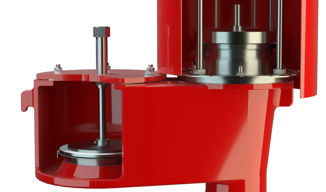
Due to our highly developed manufacturing technology, the tank pressure is maintained up to the set pressure with a tightness that is far superior to the conventional standard. This feature is achieved by special valve seats made of high quality synthetic material or PTFE. After the excess pressure is released, the valve re-seats and provides a tight seal. The optimized fluid dynamic design of the valve body and valve pallet is a result of many years of research, resulting in a stable operation of the valve pallet, optimized performance, and reduced product losses.
Dimensiones
To select the nominal size (DN), use the flow capacity chart on the following page
| DN | 50 / 2" | 80 / 3" | 100 / 4" | 150 / 6" | 200 / 8" |
| a | 376 / 14.80 | 521 / 20.51 | 563 / 22.17 | 687 / 27.05 | 952 / 37.48 |
| a | (543 / 21.38)* | (681 / 26.81)* | |||
| b | 180 / 7.09 | 250 / 9.84 | 300 / 11.81 | 350 / 13.78 | 560 / 22.05 |
| b | (405 / 15.94)* | (500 / 19.68)* |
Dimensiones en mm / pulgadas
* Dimensions in brackets only for PVDF
Selección de materiales para la vivienda
| Design | A | B | C |
| Housing | PE | PP | PVDF |
| Valve seats | PE | PP | PVDF |
| Sealing | FPM | FPM | FPM |
| Valve pallet | A, C, D | B, C, D | C, D |
Special materials upon request
Selección de materiales para la válvula de presión
| Design | A | B | C | D |
| Pressure range [mbar] [inch W.C.] | +6,0 up to +16 +2.4 up to +6.4 | +5,5 up to +16 +2.2 up to +6.4 | +9,5 up to +30 +3.8 up to +12 | +30 up to +100 +12 up to +40 |
| Valve pallet | PE | PP | PVDF | Hastelloy |
| Sealing | PTFE | PTFE | PTFE | PTFE |
| Spindle guide | PE | PP | PVDF | Hastelloy |
| Weights | PE | PP | PVDF | Hastelloy |
Special materials and other pressure Settings are available upon request
Tipo de bridas de conexión
| EN 1092-1; Form B1 |
| ASME B16.5 CL 150 F.F. |
other types upon request
Modelo y especificación
The valve pallet is weight-loaded, and the highest pressure levels are only attained with metal disks.Additional special devices available upon request.
Settings
| Pressure: | +6.0 mbar | +100 mbar |
| +2.4 inch W.C. | +40 inch W.C. | |
| +4.0 mbar | +100 mbar | |
| +1.6 inch W.C. | +40 inch W.C. | |
| +4.5 mbar | +100 mbar | |
| +1.8 inch W.C. | +40 inch W.C. |
Higher pressure settings upon request.
Diagrama de flujo volumétrico
Los diagramas de flujo volumétrico han sido determinados con un banco de pruebas de caudal calibrado y certifi - cado por TÜV. El flujo volumétrico V. en [m³/h] y el CFH se refi eren a las condiciones estándar de referencia de aire según ISO 6358 (20°C, 1bar). La conversión a otras densidades y temperaturas están referidas en el Vol. 1: “Fundamentos Técnicos”.