UB/DF
Pressure Diaphragm Valve deflagration- and endurance burning-proof
- excellent tightness, resulting in lowest possible product losses and environmental pollution
- set pressure close to opening pressure for optimum pressure maintenance in the system
- high flow capacity
- can be used as a protective system in areas with potentially explosive atmospheres in accordance with ATEX
- protection against atmospheric deflagrations and endurance burning for products up to explosion group IIB3 (NEC group C MESG ≥ 0.65 mm)
- minimum pressure loss of the PROTEGO® flame arrester unit
- flame arrester venting and ventilation of the pressurized chamber
- optimal frost protection
- automatic condensate drain
- monitoring of the load liquid by level indicator
- easy operation monitoring and maintenance by simply opening the hinged valve cap
- modular design enables replacement of individual FLAMEFILTER® discs and diaphragm
- particularly suitable for problematic products such as styrene, acrylates, etc.
Function and Description
The PROTEGO® UB/DF diaphragm valve is a worldwide unique deflagration-proof and endurance burning-proof pressure relief valve combining the function of a dynamic and static flame arrester. It is primarily used as a device for flame transmission-proof out-breathing on tanks, containers, and process equipment. The valve offers reliable protection against overpressure, prevents the in-breathing of air and product losses almost up to the set pressure, and protects against atmospheric deflagration and endurance burning if stabilized burning occurs. The PROTEGO® UB/DF diaphragm valve has proven itself over many years under a wide variety of operating conditions in the mineral oil and chemical industries. The set pressure is adjusted with a freeze resistant water-glycol mixture which ensures safe operation under extreme cold weather conditions. The PROTEGO® UB/DF valve is available for substances from explosion group IIB3 (NEC group C MESG ≥ 0.65 mm).
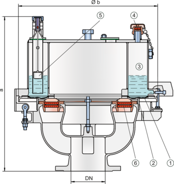
When the pressure in the tank reaches the set pressure, the diaphragm (1) on the outer valve seat ring (2) is lifted and vapors are released into the environment. The set pressure is adjusted by the weight of the liquid load (water-glycol mixture) in the outer ring chamber (3). The overpressure chamber is equipped with an opening (4) to keep the pressure in balance. The opening is equipped with a FLAMEFILTER® to prevent flame transmission into the overpressure chamber. The overpressure setting is determined by the filling level of the loading liquid and can be adjusted by a floating level indicator (5).
The tank pressure is maintained up to the set pressure with a tightness that is above the normal standards due to our highly developed manufacturing technology. This is achieved by the liquid loaded diaphragm pressing tightly around the special designed valve seat surface area even when the operating pressure increases, which reduces surface pressure and unnecessary leakage. After the overpressure is released, the valve re-seats and provides a tight seal.
If the set pressure is exceeded, explosive gas/product vapor/air mixtures are released into the atmosphere. The speed at which these mixtures exit the annular gap between the diaphragm and the outer valve seat ring is considerably greater than the flame speed. If this mixture ignites, flashback into the tank is prevented. If the mixture flow continues, the dynamic flame arresting feature prevents flashback, even in the case of endurance burning. Even at relatively low flow rates, e.g., during thermal out-breathing, the gap formed by the volumetric flow is so narrow, that flames in the gap are extinguished, and a flashback is prevented. At very low pressure settings, the explosion pressures resulting from an atmospheric deflagration may be strong enough to lift the diaphragm off the valve seat rings. The ignition into the tank can be prevented by installing the PROTEGO® flame arrester unit (8). This PROTEGO® flame arrester unit provides additional protection against atmospheric deflagration when the valve is open for maintenance and inspection.
The valve can be used at an operating temperature of up to +60°C/140°F and meets the requirements of European tank design standard EN 14015 (Appendix L) and ISO 28300 (API 2000).
Type-approved in accordance with the current ATEX Directive and EN ISO 16852, as well as other international standards.
Dimensions
To select the nominal size (DN), please use the flow capacity charts on the following pages
| DN | pressure | pressure | 80 / 3" | pressure | pressure | 100 / 4" | pressure | pressure | 150 / 6" |
| a | up to +28 mbar | up to +11.2 inch W.C. | 615 / 24.21 | up to +28 mbar | up to +11.2 inch W.C. | 645 / 25.39 | up to +25 mbar | up to +10 inch W.C. | 680 / 26.77 |
| a | > +28 mbar | > +11.2 inch W.C. | 765 / 30.12 | > +28 mbar | > +11.2 inch W.C. | 795 / 31.30 | > +25 mbar | > +10 inch W.C. | 830 / 32.68 |
| b | 410 / 16.14 | 485 / 19.09 | 590 / 23.23 |
Material selection for housing
| Design | B | C | D |
| Housing | Cast Iron | Steel | Stainless Steel |
| Valve top | Stainless Steel | Stainless Steel | Stainless Steel |
| Heating coil (UB / DF-H-...) | Stainless Steel | Stainless Steel | Stainless Steel |
| Valve seat | Stainless Steel | Stainless Steel | Stainless Steel |
| Gasket | FPM | FPM | PTFE |
| Diaphragm | A, B | A, B | A, B |
| Flame arrester unit | A | C | C |
Material selection
| Design | A | B |
| Diaphragm | FPM | FEP |
Material combinations of flame arrester unit
| Design | A | C |
| FLAMEFILTER® cage | Cast Iron | Stainless Steel |
| FLAMEFILTER® | Stainless Steel | Stainless Steel |
| Spacer | Stainless Steel | Stainless Steel |
Selection of explosion group
| MESG | Expl. Gr. (IEC / CEN) | Gas Group (NEC) |
| ≥ 0,65 mm | IIB3 | C |
Flange connection type
| EN 1092-1; Form B1 |
| ASME B16.5 CL 150 R.F. |
Design Types and Specifications
The diaphragm is pressurized by liquid. Higher pressures can be achieved upon request with a special liquid reservoir.
There are two different designs:
Pressure diaphragm valve, basic design | UB/DF - – |
Pressure diaphragm valve with heating coil (max. heating fluid temperature +85°C / 185°F) | UB/DF - H |
In addition to the standard design, a series of specially developed designs, which are particularly suitable for operating conditions to which these products are subjected, can be provided upon request (for example, for acrylics or styrene storage tanks, etc.).
Settings
| DN 80 | +3.5 mbar | +50 mbar | |
| +1.4 inch W.C. | +20 inch W.C. | ||
| DN 100 | +3.5 mbar | +45 mbar | |
| +1.4 inch W.C. | +18 inch W.C. | ||
| DN 150 | +3.5 mbar | +46 mbar | |
| +1.4 inch W.C. | +18.4 inch W.C. |
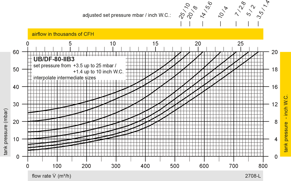
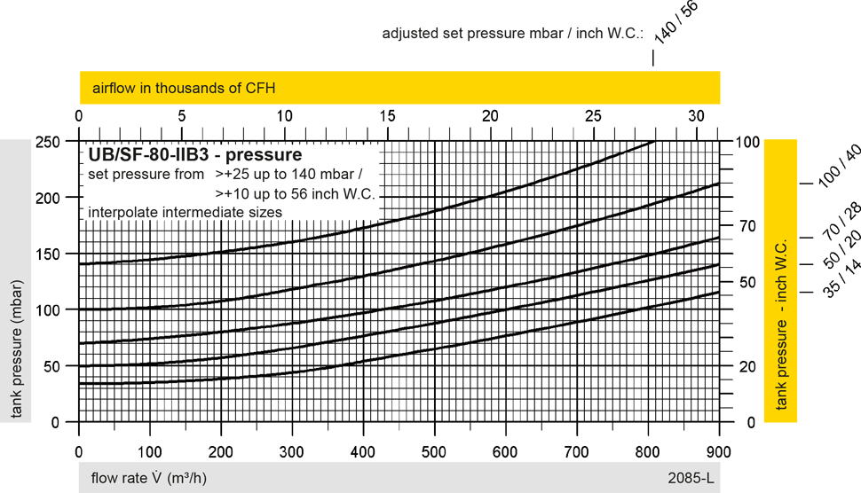
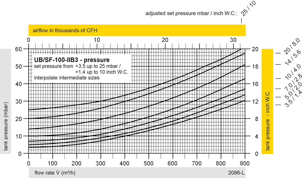
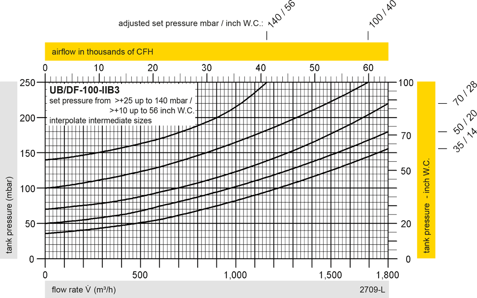
Flow Capacity Chart
UB/DF DN80 Pressure
UB/DF DN100 Pressure
UB/DF DN150 Pressure
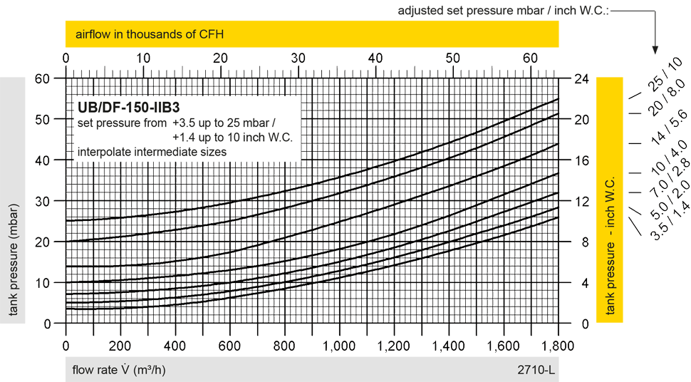
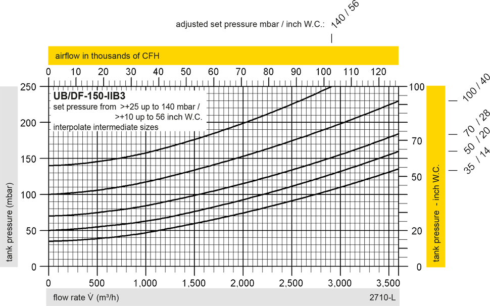
The flow capacity charts have been determined with a calibrated and TÜV certified flow capacity test rig. Volume flow V in (m³/h) and CFH refer to the standard reference conditions of air ISO 6358 (20°C, 1bar). For conversion to other densities and temperatures refer to Sec. 1: “Technical Fundamentals”.