FA-CN-IIA1
In-Line Deflagration Flame Arrester for biogas, sewage gas and landfill gas, concentric design, bidirectional
- state of the art design for bio-, sewage- and landfill gas applications
- design available for elevated operating temperatures and pressures
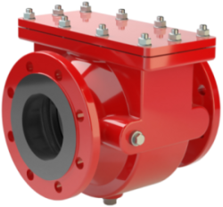
- compact design with easy access cover
- easy maintenance without disassembling of the pipeline
- modular flame arrester unit enables individual FLAMEFILTER® to be replaced and cleaned
- bidirectional flame transmission proof design
- provides protection against deflagrations and endurance burning for explosion group IIA1– methane (former designation Expl.gr. I)
- lowest pressure drop results in low operating and lifecycle costs
- modular design reduces spare parts cost
Function and Description
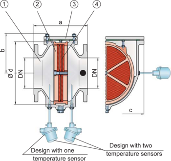
The deflagration and endurance burning-proof PROTEGO® FA-CN-IIA1 in-line flame arrester was specially developed for bio-, sewage- and landfill-gas applications. With this device it is possible to protect compressors with high operating pressures and high operating temperatures. It can also be used as an endurance-burning-proof in-line device under atmospheric conditions, without temperature monitoring. The PROTEGO® FA-CN-IIA1 deflagration flame arrester is a compact design utilizing an easy access cover for easy maintainability. The FLAMEFILTER® unit can be removed and cleaned within moments without having to disassemble the pipe. When installing the deflagration flame arrester, make sure that the distance between potential ignition sources and the location of the installed device, does not exceed the L/D ratio (pipe length/ pipe diameter), for which the device was tested. For this device the (L/D)max ratio is 50.
The in-line deflagration flame arrester is symmetrical and offers bidirectional flame transmission protection. The device consists of a housing (1) with an easy access cover (3) and the PROTEGO® flame arrester unit (2) in the center. The PROTEGO® flame arrester unit is modular and consists of several FLAMEFILTER® discs (3) and spacers firmly held in a FLAMEFILTER® casing. The number of FLAMEFILTER® discs and their gap size depend on the arrester‘s conditions of use.
By indicating the operating parameters such as temperature, pressure, explosion group and the composition of the fluid, the optimum deflagration flame arrester can be selected from a series of approved devices. This version of PROTEGO® FA-CN-IIA1 flame arrester protects against deflagrations and endurance burning of explosion group IIA1 – methane (former designation Expl.gr. I).
PROTEGO® FA-CN devices for substances of explosion groups IIA, IIB3 and IIC (NEC groups D, C, and B) are shown on separate pages.
The standard design can be used up to an operating temperature of +60°C / 140°F and an absolute operating pressure up to 2.0 bar / 29.0 psi (DN 40/1½" and DN 50/2”) or 1,6 bar / 23.2 (DN 80/3” to DN 300/12”). Devices with special approval can be obtained for higher pressures (see table 3) and higher temperatures upon request.
EU conformity according to the currently valid ATEX directive. Approvals according to other national/international regulations on request.
Dimensions
To select the nominal size (DN), please use the flow capacity charts on the following pages
| DN | 40 / 1½" | 50 / 2" | 65 / 2½" | 80 / 3" | 100 / 4" | 125 / 5" | 150 / 6" | 200 / 8" | 250 / 10" | 300 / 12" |
| a | 210 / 8.27 | 215 / 8.46 | 235 / 9.25 | 240 / 9.45 | 265 / 10.43 | 305 / 12.01 | 310 / 12.20 | 300 / 11.81 | 320 / 12.60 | 350 / 13.78 |
| b | 105 / 4.13 | 105 / 4.13 | 105 / 4.13 | 132 / 5.2 | 150 / 5.91 | 197 / 7.75 | 197 / 7.75 | 220 / 8.66 | 260 / 10.24 | 295 / 11.61 |
| c | 200 / 7.87 | 200 / 7.87 | 260 / 10.24 | 260 / 10.24 | 308 / 12.13 | 415 / 16.34 | 415 / 16.34 | 446 / 17.56 | 520 / 20.47 | 600 / 23.62 |
| d | 130 / 5.12 | 130 / 5.12 | 185 / 7.28 | 185 / 7.28 | 220 / 8.66 | 310 / 12.20 | 310 / 12.20 | 355 / 13.98 | 420 / 16.54 | 490 / 19.29 |
Material selection
| Design | A | B | |
| Housing | Steel | Stainless Steel | |
| Cover | Steel | Stainless Steel | |
| Gasket | WS 3822 * | PTFE | |
| Flame arrester unit | Stainless Steel | Stainless Steel |
Selection of explosion group
| MESG | Expl. Gr. (IEC / CEN) |
| > 1.14 mm | IIA1 (I) |
Selection of max. operating pressure
| DN | 40 / 1½" | 50 / 2" | 65 / 2½" | 80 / 3" | 100 / 4" | 125 / 5" | 150 / 6" | 200 / 8" | 250 / 10" | 300 / 12" |
| Pmax | 2.0 / 29.0 | 2.0 / 29.0 | 1,6 / 23.2 | 1,6 / 23.2 | 1,6 / 23.2 | 1,6 / 23.2 | 1,6 / 23.2 | 1,6 / 23.2 | 1,6 / 23.2 | 1,6 / 23.2 |
| Pmax | 2,5 / 36.3 | 2,5 / 36.3 | 2,5 / 36.3 | 2,5 / 36.3 | 2,5 / 36.3 | 2,5 / 36.3 | 2,5 / 36.3 | 2,5 / 36.3 | ||
| Pmax | 4,5 / 65.3 | 4,5 / 65.3 | 4,5 / 65.3 | 4,5 / 65.3 | 4,5 / 65.3 | 4,5 / 65.3 | 4,5 / 65.3 | |||
| Pmax | 5 / 72.5 | 5 / 72.5 |
Specification of max. operating temperature
| ≤ 60°C / 140°F | Tmaximum allowable operating temperature in °C |
| - | Designation |
Flange connection type
| EN 1092-1; Form B1 |
| ASME B16.5 CL 150 R.F. |
Design Types and Specifications
There are three different designs:
Basic in-line deflagration flame arrester | FA-CN - – |
In-line deflagration flame arrester with integrated temperature sensor* as additional protection against short-time burning from one side | FA-CN - T |
In-line deflagration flame arrester with two integrated temperature sensors* for additional protection against short-time burning from both sides | FA-CN - TB |
Additional special devices available upon request
*Resistance thermometer for device group II, category (1) 2 (GII cat. (1) 2)
Flow Capacity Chart
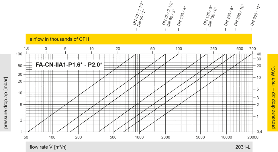
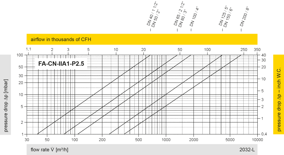
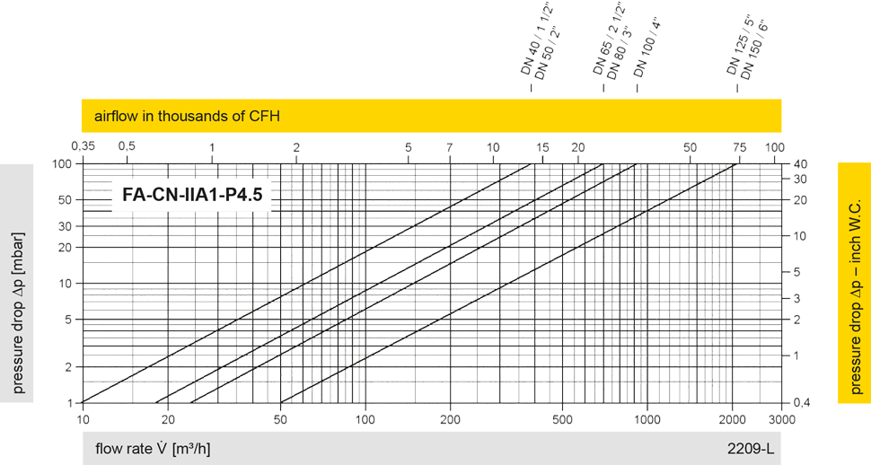
The flow capacity charts have been determined with a calibrated and TÜV certified flow capacity test rig. Volume flow V in (m³/h) and CFH refer to the standard reference conditions of air ISO 6358 (20°C, 1bar). For conversion to other densities and temperatures refer to Sec. 1: “Technical Fundamentals”.