D/PA(L)-F
Pressure or Vacuum Relief Valve com bocal de conexão para o tubo coletor de escape
- tecnologia de 10% para o aumento mínimo de pressão até o curso pleno
- estanqueidade extrema que garante uma perda de produtos mínima e um impacto ambiental reduzido
- pressão de ajuste bem próxima a pressão de abertura o que permite uma ótima conservação da pressão no sistema
- alta capacidade de vazão
- utilizável em áreas com risco de explosões
- autodrenagem de condensado
- construção de fácil manutenção
- a melhor tecnologia para tanques API
Função e descrição
The VD/SV-PA(L)-F type PROTEGO® valve is a highly developed pressure and vacuum relief valve with excellent flow performance. Typically, the valve is installed in the in-breathing and out-breathing lines of tanks, vessels, and process equipment to protect against unallowable overpressure and underpressure. The valve prevents emission losses almost up to the set pressure and prevents air intake almost up to the set vacuum. The product vapors can be released through a collective line connected to the line flange on the pressure side. Backflow is not possible, i.e. the valve can be used as an overflow valve or backflow protection.
The device will start to open as soon as the set pressure is reached and only requires 10% overpressure to full lift. Continuous investments in and a commitment to research and development have allowed PROTEGO® to develop a low pressure valve which has the same opening characteristic as a high pressure safety relief valve. This “full lift type” technology allows the valve to be set at just 10% below the maximum allowable working pressure or vacuum (MAWP or MAWV) of the tank and still safely vent the required mass flow. The opening characteristic is the same for pressure and vacuum relief.
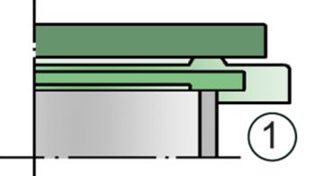
Due to our highly developed manufacturing technology, the tank pressure is maintained up to set pressure with a tightness that is far superior to the conventional standard. This feature is ensured by valve seats made of high quality stainless steel and with individually lapped valve pallets (1) and a sturdy housing design. After the excess pressure is released or the vacuum is balanced, the valve reseats and provides a tight seal.
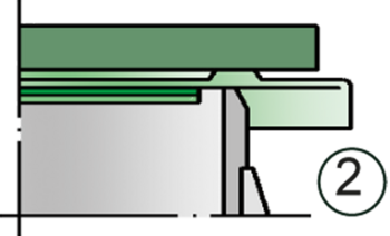
The optimized fluid dynamic design of the valve body and valve pallet is a result of many years of research, resulting in a stable operation of the valve pallet, optimized performance, and reduced product losses.
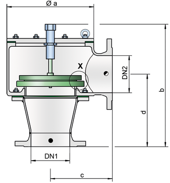
Tabela de dimensões
Para escolher o diâmetro nominal (DN), veja os diagramas de vazão nas páginas seguintes
| VD / SV-PA | |||||||
| DN 1 | 50 / 2" | 80 / 3" | 100 / 4" | 150 / 6" | 200 / 8" | 250 / 10" | 300 / 12" |
| DN 2 | 50 / 2" | 80 / 3" | 100 / 4" | 150 / 6" | 200 / 8" | 250 / 10" | 300 / 12" |
| a | 405 | 480 | 600 | 805 | 925 | 1010 | 1010 |
| b | 390 | 485 | 550 | 660 | 780 | 875 | 875 |
| c | 150 | 180 | 200 | 250 | 300 | 305 | 305 |
| d | 240 | 300 | 330 | 390 | 480 | 555 | 582 |
| e | 165 | 192 | 240 | 350 | 390 | 460 | 460 |
| VD / SV-PAL | |||||||
| DN 1 | 50 / 2" | 80 / 3" | 100 / 4" | 150 / 6" | 200 / 8" | 250 / 10" | 300 / 12" |
| DN 2 | 80 / 3" | 100 / 4" | 150 / 6" | 200 / 8" | 250 / 10" | 300 / 12" | 350 / 14" |
| a | 395 | 445 | 565 | 770 | 895 | 1010 | 1010 |
| b | 400 | 485 | 550 | 655 | 775 | 875 | 885 |
| c | 140 | 143 | 165 | 216 | 267 | 305 | 305 |
| d | 255 | 308 | 355 | 417 | 505 | 582 | 603 |
| e | 165 | 192 | 240 | 350 | 390 | 460 | 460 |
Seleção do material do corpo
| Design | A DN50/2”-80/3” | B DN100/4”-300/12” | C DN50/2”-300/12” |
| Housing | Stainless Steel | Steel | Stainless Steel |
| Housing attachment | Steel | Steel | Stainless Steel |
| Heating jacket(D/PA(L)-H-...) | Stainless Steel/Steel | Stahl | Stainless Steel |
| Valve seat | Stainless Steel | Stainless Steel | Stainless Steel |
| Gasket | PTFE | PTFE | PTFE |
Seleção de material do obturador da válvula
| Design | A | B | C | D | E | F |
| Pressure range [mbar] [inch W.C.] | ±2,0 up to ±3,5 ±0.8 up to ±1.4 | ±3,5 up to ±14 ±1.4 up to ±5.6 | ±14 up to ±35 ±5.6 up to ±14 | ±35 up to± 60 ±14 up to ±24 | ±14 up to ±35 ±5.6 up to ±14 | ±35 up to ±60 ±14 up to ±24 |
| Valve pallet | Aluminium | Stainless Steel | Stainless Steel | Stainless Steel | Stainless Steel | Stainless Steel |
| Sealing | FEP | FEP | Metal to Metal | Metal to Metal | PTFE | PTFE |
Tipo de conexão flangeada
| EN 1092-1; Form B1 |
| ASME B16.5 CL 150 R.F. |
Versão e especificação
Os obturadores de válvula são calibrados por peso. Para pressões de ajuste mais altas está disponível, sob solicitação, uma versão especial calibrada por mola. A versão (L) deve ser escolhida quando o bocal de conexão para o tubo coletor de escape é um diâmetro nominal maior que o diâmetro nominal do bocal do tanque.
Estão disponíveis quatro versões:
Pressure or vacuum valve in basic design | D/PA-F |
Pressure or vacuum valve with heating jacket | |
Pressure or vacuum relief valve with DN2 > DN1 | D/PAL-F - H |
Pressure or vacuum relief valve with DN2 > DN1 with heating jacket | D/PAL - H |
Additional special devices available upon request
Ajustes de pressão
| (DN 25/1" up to 200/8") | ±60 mbar | ±500 mbar | |
| ±24 inch W.C. | ±200 innch W.C. | ||
| (DN 250/10") | |||
Diagrama de vazão
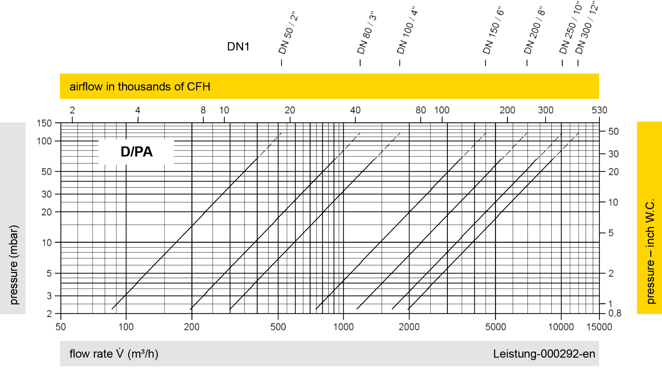
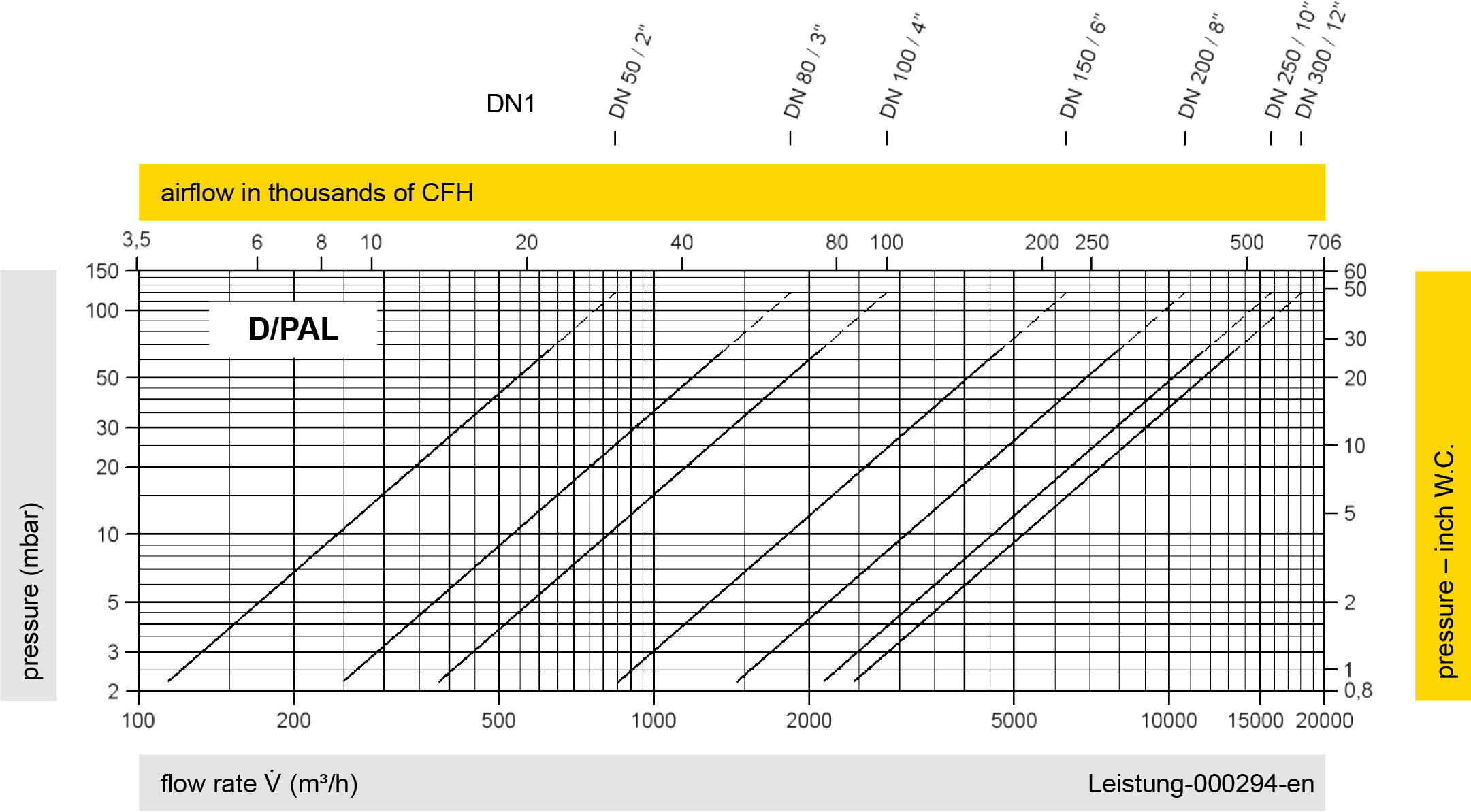
Este diagrama de vazão foi determinado em uma bancada de medição de vazão calibrada e certificada pela TÜV. A vazão V em m³/h se refere ao estado técnico padrão de ar, conforme ISO 6358 (20°C, 1bar). Para conversão em outras densidades e temperaturas, veja o cap. 1: Bases técnicas.