UB/SF-IIA1
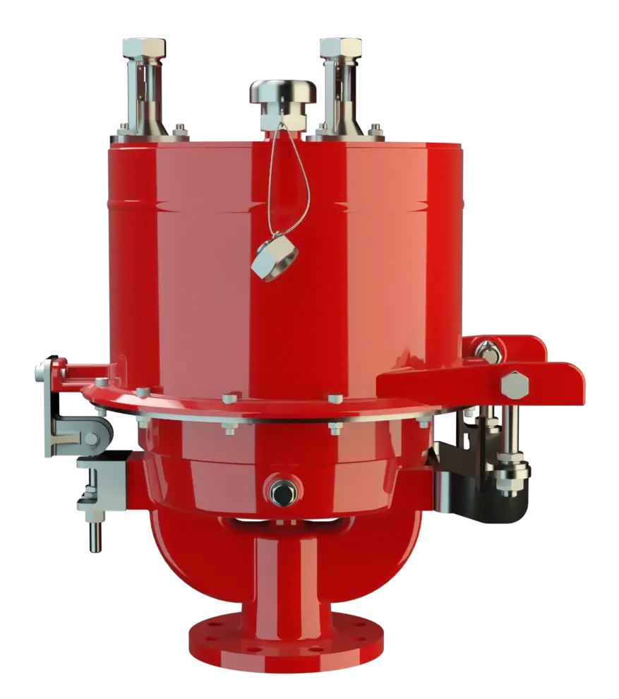
Pressure/Vacuum Diaphragm Valve with internal coating, deflagration- and endurance burning-proof
Características
Função e descrição
Combined Pressure and Vacuum Relief Valve
The Deflagration-Proof and Endurance-Burning-Proof PROTEGO® UB/SF-IIA1 type diaphragm valve is a state of the art pressure and vacuum- relief valve combining the function of a dynamic Flame Arrester. Worldwide this design is unique. It is primarily used within biogas plants as a device for flame transmission proof in- and outbreathing on tanks, containers and process engineering apparatus. The valve offers reliable protection against excess pressure and vacuum, prevents the inbreathing of air and product losses almost up to the set pressure and protects against atmospheric deflagration and endurance burning if stabilized burning occurs.

Usable Under Extreme Climatic Conditions
The set pressure is adjusted with a freeze resistant water glycol mixture, which assures safe operation under extreme cold weather conditions. The liquid is capsuled and is not discharged or diluted during operation. The valve can also be operated at temperatures lower than 0°C without ice constricting the function of the valve.
Composition
When the pressure in the tank reaches the set pressure, the FPM-diaphragm (1) on the outer valve seat ring (2) is lifted and vapours vent to the environment. The set pressure is adjusted by the liquid (glycol water mixture) column height, which is filled into the outer ring chamber (3). The overpressure chamber is equipped with an opening (4) to keep the pressure in balance with the ambient pressure. If a vacuum builds up in the tank, it is transmitted through pressure balancing tubes into the vacuum chamber (5) (inner chamber). If the set vacuum, which depends on the liquid column height in the vacuum chamber, is reached the atmospheric pressure lifts the diaphragm up off the inner valve seat ring (6). Ambient air can now flow into the tank. The liquid column heights, which affect the set pressures and vacuum, can be checked by floating level indicators (7).
Advanced Sealing Technology for Reliable Pressure Maintenance in Tanks
The tank pressure is maintained up to the set pressure with a tightness that is far superior to the conventional standard due to our highly developed manufacturing technology. This is achieved because the liquid loaded diaphragm presses tightly around the special designed valve seat surface area, even when the operating pressure increases. This is extremely important to reduce leakage to an absolute minimum. After the excess pressure or vacuum is discharged, the valve reseats and provides a tight seal.
Dynamic Flame Arresting Safety at Overpressure Conditions
If the tank pressure exceeds the adjusted set pressure, as the case may be explosive gas/product-vapour air mixtures exit. The speed at which these mixtures exit the annular gap between the diaphragm and the outer valve seat ring while overcoming the set pressure is much faster than the flame speed. If this mixture ignites, flashback into the tank is prevented. If the mixture flow continues, the dynamic flame arresting feature prevents flashback ignition even in the case of endurance burning.
Many Individual Certifications
Even at relatively low flow rates, which occur during thermal outbreathing, the gap formed by the volumetric flow is so narrow that flames are extinguished in the gap and flashback is prevented. The PROTEGO® UB/SF-IIA1 valve is available for substances of explosion group IIA1 - methane. The valve can be used up to an operating temperature of +60°C / 140°F and an operating pressure up to ≥3.5 mbar / 1.4 inch W.C. and meets the requirements of European Tank Design Standard EN 14015 – Appendix L and API 2000 EU conformity according to the currently valid ATEX directive. Approvals according to other national/international regulations on request.
Tabela de dimensões
To select the nominal size (DN), please use the flow capacity charts on the following pages
| DN | pressure | pressure | 80 / 3" | pressure | pressure | 100 / 4" | pressure | pressure | 150 / 6" |
| a | up to +28 mbar | up to +11.2 inch W.C. | 615 / 24.21 | up to +28 mbar | up to +11.2 inch W.C. | 645 / 25.39 | up to +25 mbar | up to +10 inch W.C. | 680 / 26.77 |
| a | > +28 mbar | > +11.2 inch W.C. | 765 / 30.12 | > +28 mbar | > +11.2 inch W.C. | 795 / 31.30 | > +25 mbar | > +10 inch W.C. | 830 / 32.68 |
| b | 410 / 16.14 | 485 / 19.09 | 590 / 23.23 |
Dimensões em mm
Pressure settings > +50 mbar / +20 inch W.C. (DN 80), > +45 mbar / +18 inch W.C. (DN 100), > +46 mbar / +18.4 inch W.C. (DN150) with additional liquid reservoir - dimensions upon request
Dimensions for pressure/vacuum diaphragm valves with heating coil upon request
Material for housing
| Design | B |
| Housing | Steel |
| Coating of housing | 2 components polymere coating |
| Valve top | Stainless Steel |
| Heating coil (UB / SF-H-...-I) | Stainless Steel |
| Valve seats | Stainless Steel |
| Gasket | FPM |
| Diaphragm | FPM |
Special materials upon request
Seleção do grupo de explosão
| MESG | Expl. Gr. (IEC / CEN) |
| ≥ 1,14 mm | IIA1 |
Special approvals upon request
Tipo de conexão flangeada
| EN 1092-1; Form B1 |
| ASME B16.5 CL 150 R.F. |
other types upon request
Versão e especificação
Almost any combination of vacuum and pressure settings can be utilized for the valve. The diaphragm is pressurized by liquid. Higher pressures can be achieved upon request with a special liquid reservoir.Settings:
| DN 80 | +3.5 mbar | +50 mbar |
| +1.4 inch W.C. | +20 inch W.C. | |
| DN 100 | +3.5 mbar | +45 mbar |
| +1.4 inch W.C. | +18 inch W.C. | |
| DN 150 | +3.5 mbar | +46 mbar |
| +1.4 inch W.C. | +18.4 inch W.C. | |
| Vacuum | -3.5 mbar | -35 mbar |
| -1.4 inch W.C. | -14 inch W.C. |
Higher pressure settings up to +150 mbar (60 inch W.C.) in special design with additional liquid reservoir upon request.
Diagrama de vazão
UB/SF DN80
UB/SF DN100
UB/SF DN150
Este diagrama de vazão foi determinado em uma bancada de medição de vazão calibrada e certificada pela TÜV. A vazão V em m³/h se refere ao estado técnico padrão de ar, conforme ISO 6358 (20°C, 1bar). Para conversão em outras densidades e temperaturas, veja o cap. 1: Bases técnicas.