FA-G-IIA1-P2.2
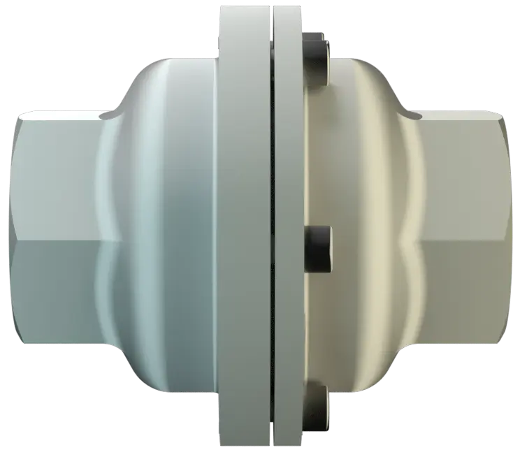
In-Line Deflagration Flame Arrester for biogas, sewage gas and landfi ll gas, concentric design, bidirectional, endurance burning proof (under atmospheric conditions)
Características
Função e descrição
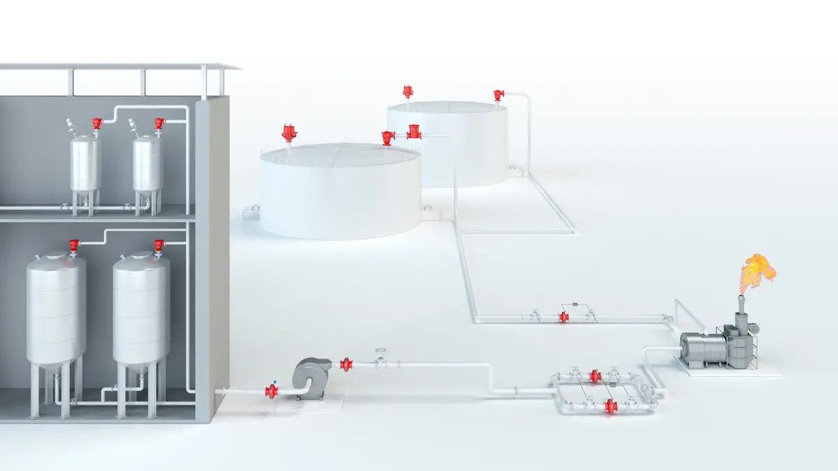
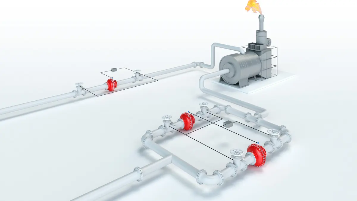
Protection of Fuel Supply Lines
The PROTEGO® FA-G-IIA1-P2.2 In-Line Deflagration Flame Arrester Deflagration flame arrester Flame arrester designed to prevent the transmission of a deflagration. It can be an end-of-line flame arrester or an in-line flame arrester. was specially developed for bio-, sewage- and landfill-gas applications. The compact design of the PROTEGO® FA-G makes it the state of the art technology for installation in pipes with diameters of ½” up to 2”. The devices are installed with minimal distance to the burner to prevent flashback Flashback Phenomenon occurring in a flammable mixture of air and gas when the local velocity of the combustible mixture becomes less than the flame velocity, causing the flame to travel back to the point of mixture. in to the fuel feed lines. When installing the deflagration Deflagration Explosion propagating at subsonic velocity. flame arrester Flame arrester Device fitted to the opening of an enclosure, or to the connecting pipe work of a system of enclosures, and whose intended function is to allow flow but prevent the transmission of a flame. , make sure that the distance between potential ignition sources and the location of the installed device Device A device is a pipe component that influences the media flow by opening, closing, or partially shutting off the flow channel or by dividing or mixing the media flow. , does not exceed the L/D ratio (pipe length/pipe diameter), for which the device was approved. As per EN ISO 16852 the L/D ratio is limited to (L/D) max ≤ 50 for Deflagration Flame Arresters of explosion Explosion Abrupt oxidation or decomposition reaction producing an increase in temperature, pressure, or in both simultaneously. group IIA1.
For Explosion Group IIA1 - Methan
The In-Line Deflagration Flame Arresters is symmetrical and offers bidirectional flame transmission protection. The device consists of two housing Housing A housing is a solid shell, which surrounds a content, either protecting the content from external influences, or protecting the environment from the content. parts (1) and two FLAMEFILTER® (2) in the center. The PROTEGO® FA-G-IIA1-P2.2 Flame Arrester protects against deflagrations and endurance burning Endurance burning Stabilized burning for an unlimited time. (under atmospheric condition Atmospheric conditions Atmospheric conditions are pressures from 80 kPa till 110 kPa and temperatures from -20°C up to +60°C. ) and short time burning Short time burning Stabilized burning for a specific time. for 1 min. for the maximum operating conditions of explosion Explosion Abrupt oxidation or decomposition reaction producing an increase in temperature, pressure, or in both simultaneously. group IIA1 - Methane.

Many Individual Certifications
PROTEGO® FA-G devices for substances of explosion Explosion Abrupt oxidation or decomposition reaction producing an increase in temperature, pressure, or in both simultaneously. groups IIA, IIB3 and IIC (NEC groups D, C, and B) are shown on separate pages. The standard design can be used up to an operating temperature Operating temperature Temperature reached when the equipment is operating under design conditions. of +60°C / 140°F and an absolute operating pressure Operating pressure Operating pressure is the pressure existing at normal operating conditions within the system being protected. up to 2.2 bar / 31.9 psi. EU conformity according to the currently valid ATEX directive. Approvals according to other national/international regulations on request.
Tabela de dimensões
Para escolher o diâmetro nominal (DN), veja os diagramas de vazão nas páginas seguintes
| DN | G ½ | G ¾ | G 1 | G 1 ¼ | G 1 ½ | G 2 |
| a | 80 | 80 | 100 | 100 | 155 | 155 |
| b | 55 | 55 | 76 | 76 | 124 | 124 |
| c | 10 | 100 | 110 | 110 | 170 | 170 |
| d | — | — | -— | — | 400 | 400 |
| SW | 32 | 32 | 50 | 50 | 75 | 75 |
Dimensions in mm / inches, SW= width across flats
Seleção do material
| Execução | B | C |
| Corpo | Aço inoxidável | Hastelloy |
| Vedação | PTFE | PTFE |
| FLAMEFILTER®* | Aço inoxidável | Hastelloy |
* os FLAMEFILTER® também podem ser fornecidos em tântalo, Inconel, cobre etc., em caso de utilização dos materiais do corpo listados.
Materiais especiais sob solicitação.
Seleção do grupo de explosão
| MESG | Gr. expl. (IEC / CEN) |
| ≥ 1,14 mm | IIA1 |
Aprovações especiais sob solicitação
Seleção da pressão máx. de trabalho
| Expl. Gr | DN | G ½ | G ¾ | G 1 | G 1 ¼ | G 1 ½ | G 2 |
| IIA1 | Pmax | 2,2 | 2,2 | 2,2 | 2,2 | 2,2 | 2,2 |
Pmáx. = pressão de trabalho máxima admissível em bar absoluta, pressão de trabalho mais elevada sob solicitação
Indicação da temperatura máx. de trabalho
| ≤ 60°C / 140°F | Ttemperatura máxima de trabalho admissível em °C |
| - | Designation |
temperaturas de trabalho mais elevadas, sob solicitação
Tipo de conexão
| Rosca para tubo DIN ISO 228-1 | DIN |
outras conexões roscadas sob solicitação
Versão e especificação
Estão disponíveis três versões:*Termoresistência para grupo de equipamentos II, categoria (1) 2 (cat. GII (1) 2)
Diagrama de vazão
Este diagrama de vazão foi determinado em uma bancada de medição de vazão calibrada e certificada pela TÜV. A vazão V em m³/h se refere ao estado técnico padrão de ar, conforme ISO 6358 (20°C, 1bar). Para conversão em outras densidades e temperaturas, veja o cap. 1: Bases técnicas.