Características
Função e descrição
Automatic Venting Valves for Floating Roof Tanks
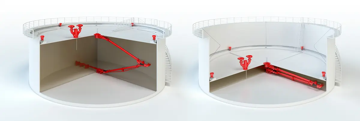
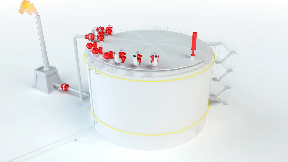
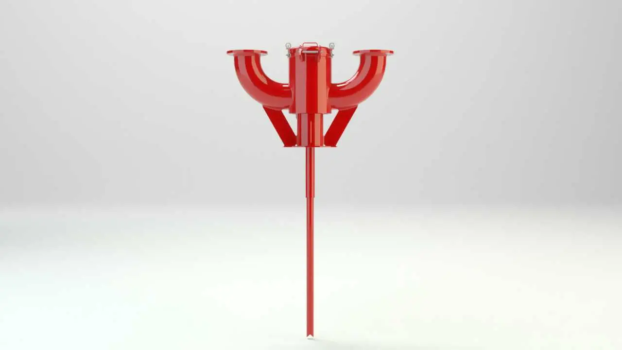
PROTEGO® Lift Lift Lift is the actual travel of the valve pallet from the main valve out of the closed position. -Actuated Vent Valves Type AL-DK provide automatic venting of floating roof Floating roof A floating roof is the roof of a tank that is fitted with floating chambers (pontoons) and lies on top of the liquid. tanks when the floating roof is lowered onto its supports and the tank is either drained or refilled. When the floating roof is in its lowest position, the valve is forced to open through lift actuation, which prevents inadmissible vacuum Vacuum Vacuum is the pressure in an enclosed space that is lower than the ambient pressure. during final draining or inadmissible pressure Pressure (gauge pressure) Pressure for which the value is equal to the algebraic difference between the absolute pressure and the atmospheric pressure. during refilling.
Design of Valves
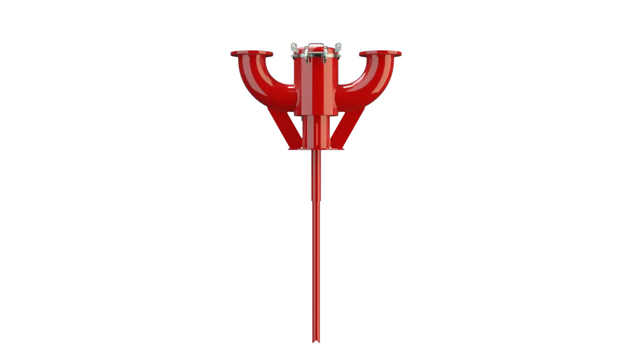
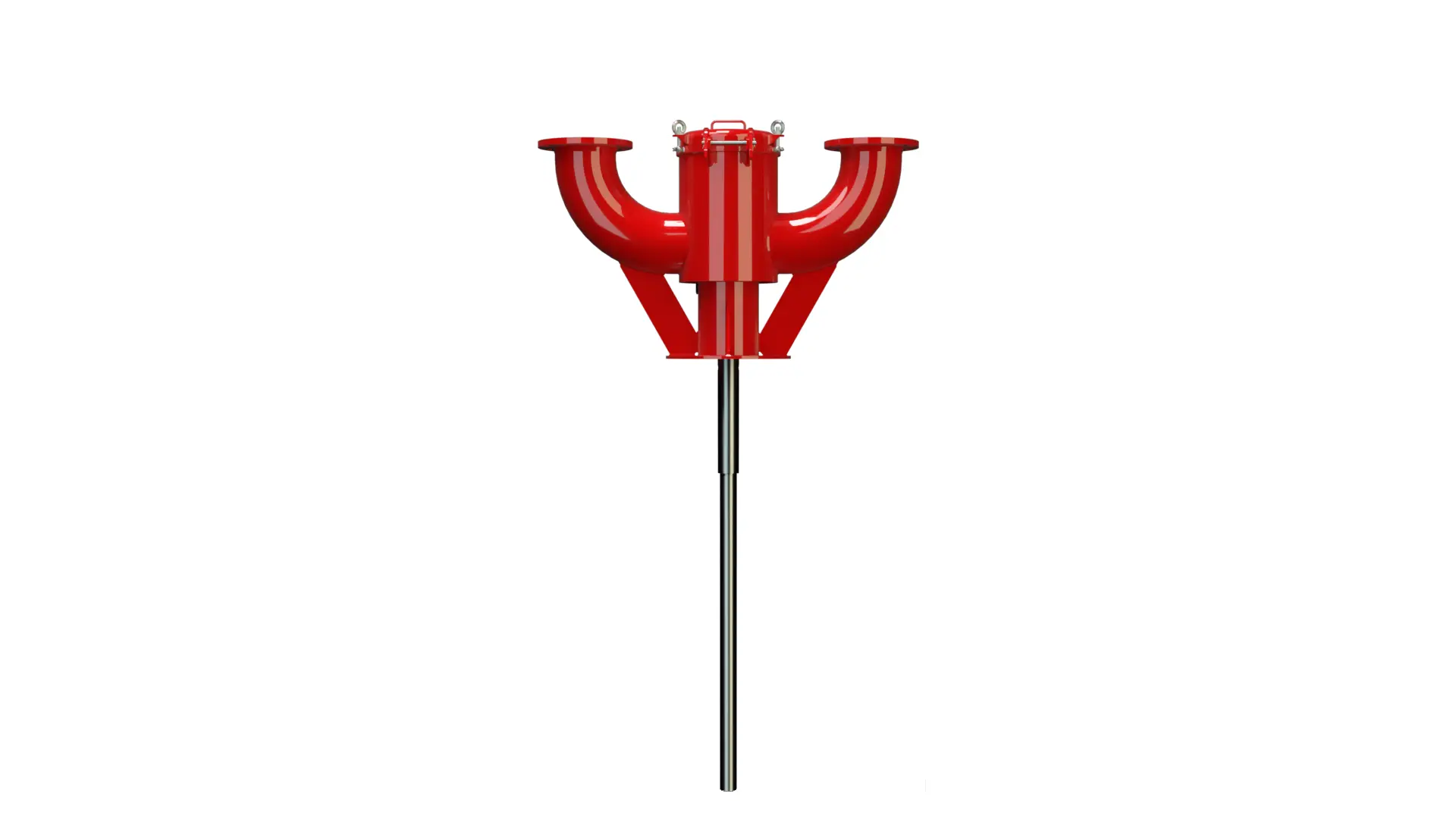
The PROTEGO® AL-DK valve consists of a housing Housing A housing is a solid shell, which surrounds a content, either protecting the content from external influences, or protecting the environment from the content. (1) with a sheet metal panel to be welded onto the floating roof or a flange for mounting on a mating flange, two or four connection nozzles (2) for installation of vent caps, cover (3), lift (4) including valve disc (5), lift pipe (6), and the condensate drain valve (7) which can be designed to be flame transmission proof. The condensate drain is sealed by a flat gasket attached to the valve disk (5). The cover (3) is sealed by a sealing cord Sealing cord A sealing cord is a synthetic cord with a circular or square profile. It is used to seal off components. (8).
Dimensions for Different Floating Roof Heights
As the lowest position of the floating roof varies for operation and assembly, specify the dimensions h1 and h2: h1: Distance between the lower edge of sheet-metal panel (or mounting flange) and the tank bottom in lowest position of floating roof (operating position with an empty tank). h2: Distance between the floating roof in lifted maintenance Maintenance Combination of all technical and administrative actions, including supervision actions, intended to maintain or restore a unit in working order. position and the height of the floating roof in fully lowered operating position (operating position with an empty tank).
Conversion of Floating Roof Supports and Extension of the Plunger
If the floating roof supports are changed from operating position to maintenance position, the lift has to be extended as well. This is done with an adjustable locking pin that is secured with a split pin. The valve is not flame transmission proof. Based on a hazard analysis with regard to material selection and function, the valves have no potential ignition sources. As a result, they are not subject to the European Explosion Explosion Abrupt oxidation or decomposition reaction producing an increase in temperature, pressure, or in both simultaneously. Protection Directive (ATEX) when used in explosive atmospheres.
Maßtabelle für AL-DK und AL-DK-4
| AL-DK | AL-DK-4 | |||||||
| DN1 | 200 / 8" | 200 / 8" | 200 / 8" | 200 / 8" | 250 / 10" | 250 / 10" | 200 / 8" | 200 / 8" |
| DN2 | 80 /3" | 100 /4" | 150 / 6" | 200 / 8" | 150 / 6" | 200 / 8" | 100 /4" | 200 / 8" |
| a | 350 / 13.78 | 350 / 13.78 | 350 / 13.78 | 350 / 13.78 | 350 / 13.78 | 350 / 13.78 | 350 / 13.78 | 350 / 13.78 |
| b | 465 / 18.31 | 465 / 18.31 | 465 / 18.31 | 515 / 20.28 | 465 / 18.31 | 515 / 20.28 | 465 / 18.31 | 650 / 25.59 |
| c | 870 / 34.25 | 870 / 34.25 | 870 / 34.25 | 870 / 34.25 | 870 / 34.25 | 870 / 34.25 | 870 / 34.25 | 870 / 34.25 |
| d | 450 / 17.72 | 450 / 17.72 | 450 / 17.72 | 450 / 17.72 | 450 / 17.72 | 450 / 17.72 | 450 / 17.72 | 600 / 23.62 |
| e | 345 / 13.58 | 360 / 14.17 | 385 / 15.16 | 415 / 16.34 | 385 / 15.16 | 415 / 16.34 | 415 / 16.34 | 415 / 16.34 |
| f | 460 / 18.11 | 445 / 17.52 | 285 / 11.22 | 370 / 14.57 | 285 / 11.22 | 367 / 14.45 | 445 / 17.52 | 370 / 14.57 |
| x | 658 / 25.91 | 920 / 36.22 | ||||||
Dimensões em mm
Material
| Corpo | Aço |
| Guia da Válvula | Aço |
| Vedação | FPM |
Materiais especiais mediante consulta
Tipo de conexão flangeada
| EN 1092-1, forma B1 ou DIN 2501, forma C, PN 16 , a patir DN 200 PN 10 | EN ou DIN |
| ASME B16.5 CL 150 R.F. | ASME |
Outras conexões mediante consulta
Dados necessários para a especificação
Produto armazenadoDiâmetro do tanque (m)
Altura do tanque (m)
Altura do suporte h1 (posição de operação com tanque vazio)
Altura do suporte h2 (posição de montagem elevada)
Pressão máxima admissível do tanque pT (mbar)
Potência da bomba (m³/h)
Seleção e Desenho
A determinação da quantidade necessária das válvulas de haste e do diâmetro nominal DN ocorre em função da vazão volumétrica calculada (m³/h), da potência da bomba e da potência térmica na posição inferior do teto flutuante e em função da pressão máxima admissível do tanque pT (mbar) de acordo com o diagrama de vazão volumétrica. São possíveis versões especiais.
As vazões volumétricas e perdas de pressão das calotas de respiro PROTEGO® BE/HR ou PROTEGO® LH/AD devem ser levados em consideração adicionalmente, de acordo com os respectivos diagramas nos folhetos específicos ou manuais de operação.
Se for desejada apenas a desaeração e ventilação podem ser aplicadas as válvulas de haste PROTEGO® AL 200.
Versão e especificação
Two designs are available:Diagrama de vazão
Este diagrama de vazão foi determinado em uma bancada de medição de vazão calibrada e certificada pela TÜV. A vazão V em m³/h se refere ao estado técnico padrão de ar, conforme ISO 6358 (20°C, 1bar). Para conversão em outras densidades e temperaturas, veja o cap. 1: Bases técnicas.
-
Lift-actuated vent valves of type PROTEGO® AL-DK can be combined with vent caps type EB which are deflagration Deflagration Explosion propagating at subsonic velocity. proof and resistant against endurance burning Endurance burning Stabilized burning for an unlimited time. . This ensures flame transmission proof ventilation.
Se não for exigida segurança contra combustão contínua, também é possível uma combinação com dispositivos à prova de deflagração do tipo PROTEGO® LH/AD. Os respectivos folhetos podem ser encontrados no capítulo 2 "Calotas de respiro".