SV/E
Vacuum Relief Valve deflagration-proof
- 10% technology for minimum pressure increase up to full lift
- excellent tightness, resulting in lowest possible product losses and reduced environmental pollution
- due to 10% technology, set pressure is close to opening pressure for optimum pressure maintenance in the system as compared to conventional 40% or 100% technology
- high flow capacity
- valve pallet is guided inside the housing to protect against harsh weather conditions
- can be used as a protective system in areas with potentially explosive atmospheres in accordance with ATEX
- FLAMEFILTER® provides protection against atmospheric deflagrations
- integrated FLAMEFILTER® saves space and weight and reduces costs
- FLAMEFILTER® is protected from clogging and sticky substances caused by product vapors
- minimum pressure loss of the PROTEGO® flame arrester unit
- maintenance-friendly design
- modular design enables replacement of individual FLAMEFILTER® discs and valve pallet
- available in a special design with lifting device (for ships)
Función y Descripción
The deflagration-proof SV/E type PROTEGO® valve is a state-of-the-art vacuum relief valve with an integrated flame arrester unit. It is primarily used as a device for flame transmission-proof in-breathing on tanks, containers, and process equipment. The valve offers reliable protection against vacuum and prevents in-breathing of air almost up to the set pressure; while at the same time protecting against atmospheric deflagration. The PROTEGO® flame arrester unit is designed to achieve minimum pressure drop with maximum safety. The PROTEGO® SV/E valve is available for substances from explosion groups IIA to IIC.
When the set vacuum is reached, the valve starts to open and reaches full lift within 10% overpressure. This unique 10% technology enables a set vacuum that is only 10% above the maximum allowable working vacuum (MAWV) of the tank. After years of development, this typical opening characteristic of a safety relief valve is now also available for the low pressure range.
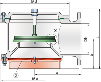
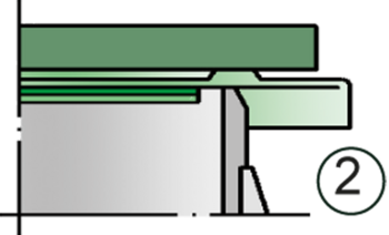
The tank pressure is maintained up to the set vacuum with a tightness that is above the normal standards due to our state-of-the-art manufacturing technology. This feature is ensured by the valve seats made of high quality stainless steel and with individually lapped valve pallets (1), or with an air cushion seal, (2) in conjunction with high quality FEP diaphragm. The valve pallets are also available with a PTFE seal to prevent them from sticking when sticky substances are used and to enable the use corrosive fluids. After the vacuum is balanced, the valve re-seats and provides a tight seal.
If the valve is used in atmospheres forming an explosive mixture with air and the mixture ignites, the integrated PROTEGO® flame arrester unit (3) prevents flame transmission into the tank.
The standard design is tested at an operating temperature of up to +60°C / 140°F and meets the requirements of European tank design standard EN 14015 (Appendix L) and ISO 28300 (API 2000). In addition, numerous versions for higher operating temperature are available.
EU conformity according to the currently valid ATEX directive. Approvals according to other national/international regulations on request. Additional certificates from classification organizations for use on ships are also available.
Modelo y especificación
The valve disc is weight-loaded. Higher vacuum can be achieved upon request with a special spring loaded design.
There are four different designs:
Vacuum relief valve, basic design | SV/E- – - – |
Vacuum relief valve with heating jacket (max. heating fluid temperature +85°C / 185°F) | SV/E- – - H |
Vacuum relief valve with lifting gear (ship design) | SV/E- S - – |
Vacuum relief valve with lifting gear (ship design) and heating jacket (max. heating fluid temperature +85°C / 185°F) | SV/E- S - H |
Additional special devices available upon request
Settings
| Vacuum: | -2.0 mbar | -60 mbar | |
| -0.8 inch W.C. | -24 inch W.C. |
Diagrama de flujo volumétrico
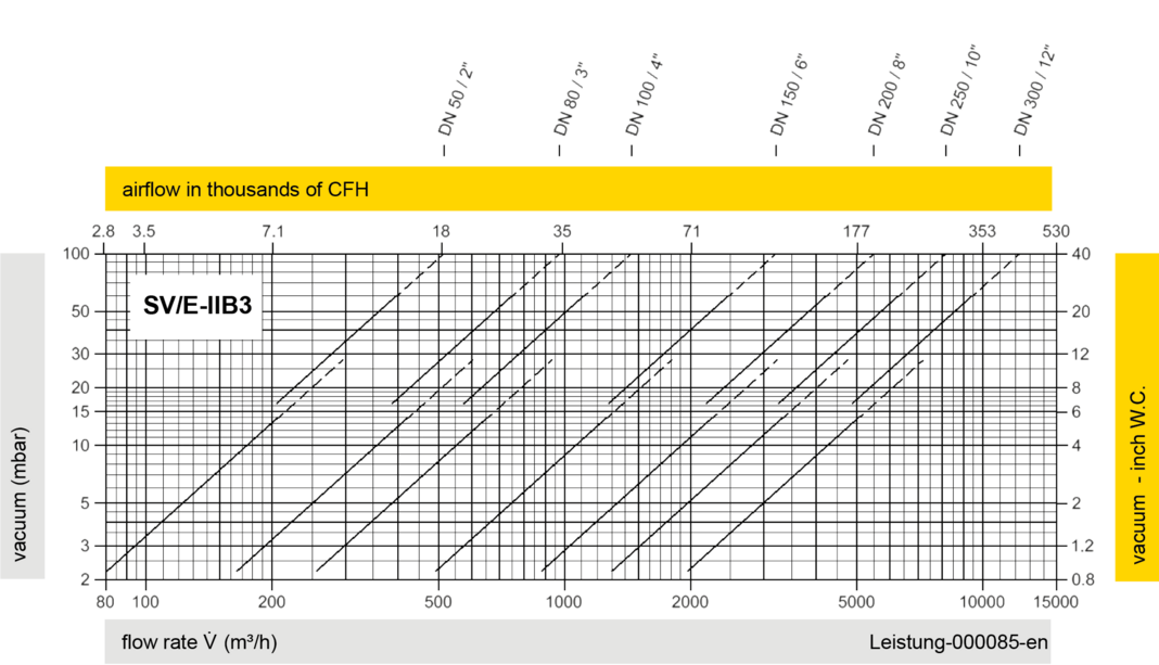
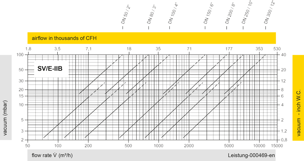
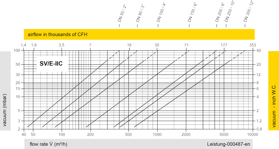
Los diagramas de flujo volumétrico han sido determinados con un banco de pruebas de caudal calibrado y certifi - cado por TÜV. El flujo volumétrico V. en [m³/h] y el CFH se refi eren a las condiciones estándar de referencia de aire según ISO 6358 (20°C, 1bar). La conversión a otras densidades y temperaturas están referidas en el Vol. 1: “Fundamentos Técnicos”.