LDA
Liquid Detonation Flame Arrester for filling lines - internal installation
- simple construction provides low risk of contamination
- low pressure loss
- provides protection against deflagrations and stable detonations
- useable for nearly all flammable liquids
- meets TRGS* requirements
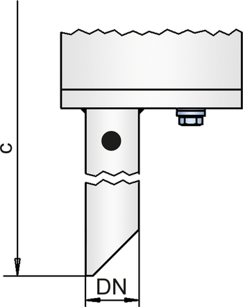
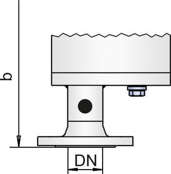
- available with different connections
Función y Descripción
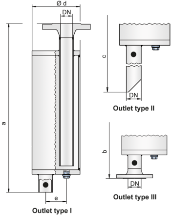
The PROTEGO® LDA series of liquid detonation arresters was developed for storage tank filling lines that are not continuously filled with product and sometimes contain a combustible mixture.
The device is installed inside the tank at the end of the line and prevents the combustion from being transferred into the tank if the explosive atmosphere ignites. The liquid detonation arresters function according to the siphon principle in which the liquid product serves as a liquid barrier to flame propagation.
When a highly accelerated pipe deflagration or detonation occurs, the combustion pressure and flame propagation speed is substantially reduced by the design, converted into a low-energy deflagration, and then stopped by the remaining immersion liquid.
The application range for the device is a product vapor/air mixture temperature of up to + 60°C / 140°F and an absolute pressure up to 1.1 bar / 15.9 psi. This covers all possible operating conditions of empty lines for flammable liquids. The liquid detonation arrester is pressure-resistant up to 10 bar / 145 psi. The device protects against nearly all flammable liquids and is approved for explosion groups IIA to IIB3 (NEC group D to C MESG ≥ 0.65 mm).
EU conformity according to the currently valid ATEX directive. Approvals according to other national/international regulations on request.
Diagrama de flujo volumétrico
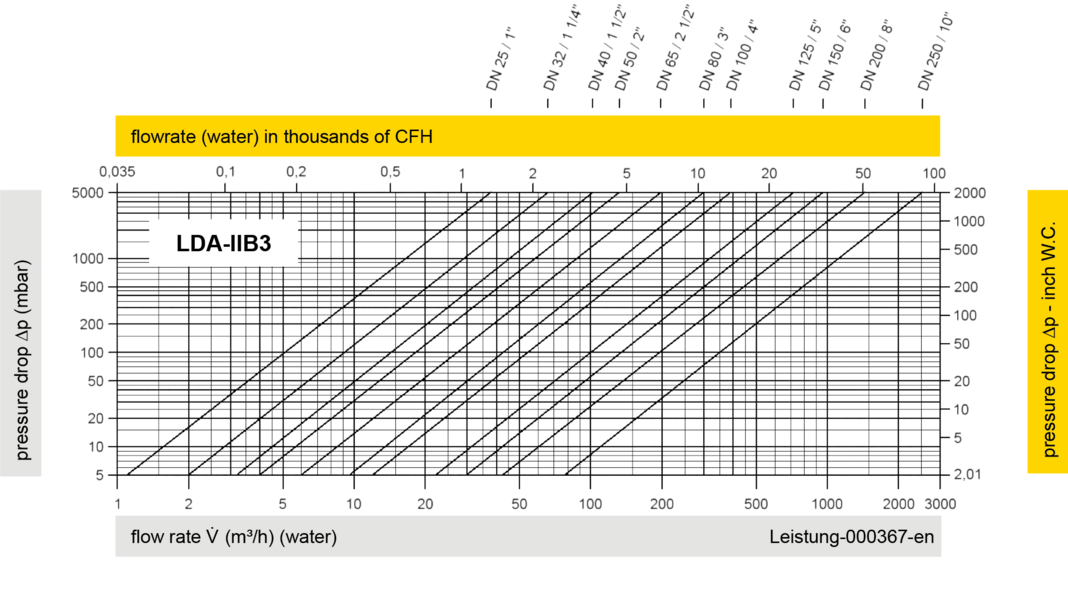

The volume flow V in m³/h was determined with water according to DIN EN 60534 at a temperature Tn = 20°C and an atmospheric pressure pn = 1,013 bar, kinematic viscosity v = 10-6 m²/s
To avoid electrostatic charge of flammable liquids the maximum flow is limited (refer to TRGS 727, CENELEC-Report CLC/TR 60079-32-1).