DZ/T
Pressure or Vacuum Relief Valve, In-Line
- 10% technology for minimum pressure increase up to full lift
- extreme tightness, resulting in lowest possible product losses and reduced environmental pollution
- based on 10% technology, set pressure is close to opening pressure for optimum pressure maintenance in the system as compared to conventional 40% or 100% technology
- high flow capacity reduces costs through the use of smaller valves
- can be used as pressure or vacuum relief valve
- can be used in explosion hazardous areas
- sturdy housing design (PN 10)
- maintenance-friendly design
Función y Descripción
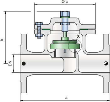
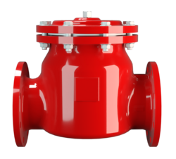
The PROTEGO® in-line valve DZ/T is a state-of-the-art pressure or vacuum relief valve. Typically, the valve is installed in the in-breathing or out-breathing lines of tanks, vessels, and process equipment to protect against unallowable overpressure or underpressure. The valve prevents emission losses almost up to the set pressure and prevents unacceptable product entry. The device will start to open as soon as the set pressure is reached and only requires 10% overpressure to full lift. Continuous investments in and a commitment to research and development have allowed PROTEGO® to develop a low pressure valve which has the same opening characteristic as a high pressure safety relief valve. This “full lift type” technology allows the valve to be set at just 10% below the maximum allowable working pressure or vacuum (MAWP or MAWV) of the tank and still safely vent the required mass flow. Due to our highly developed manufacturing technology, the tank pressure is maintained up to set pressure with a tightness that is far above the conventional standard.
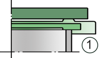
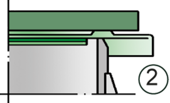
This feature is ensured by valve seats made of high quality stainless steel and with individually lapped valve pallets (1) or with an air cushion seal (2) in conjunction with high quality FEP diaphragm. The valve pallets are also available with a PTFE seal to prevent the valve pallets from sticking when sticky products are used and to enable the use of corrosive fluids. After the overpressure is released or the vacuum is balanced, the valve re-seats and provides a tight seal.
The optimized fluid dynamic design of the valve body and valve pallet is a result of many years of research, resulting in stable operation of the valve pallet, optimized performance, and reduced product losses.
Modelo y especificación
The valve pallet is weight loaded. Higher set pressures for pressure and vacuum are achieved by using spring loaded type DZ/T-F.
Two different designs are available:
In-line pressure or vacuum relief valve, standard design | DZ/T - – |
In-line pressure or vacuum relief valve with heating jacket | DZ/T - H |
Additional special devices available upon request
Within piping systems the influence of backpressure has to be considered in deciding the set pressure and opening characteristics. For special design solutions (e.g. partial load operation) the valve can be supplied with standard valve pallets (with proportional opening function).
Settings
| DN 25 and 32 | ±3.5 mbar | ±60 mbar | |
| ±1.4 inch W.C. | ±24 inch W.C. | ||
| DN 40 up to 300 | ±2.0 mbar | ±60 mbar | |
| ±0.8 inch W.C. | ±24 inch W.C. |
Diagrama de flujo volumétrico
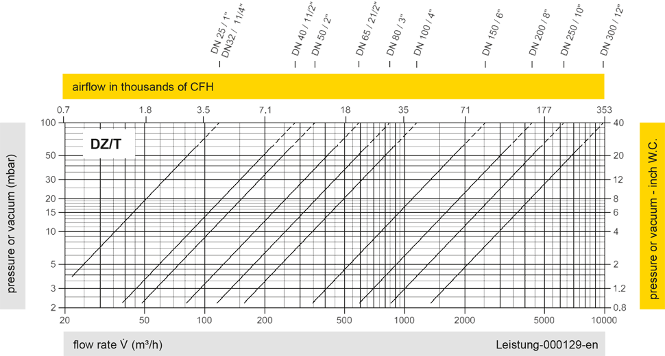
Los diagramas de flujo volumétrico han sido determinados con un banco de pruebas de caudal calibrado y certifi - cado por TÜV. El flujo volumétrico V. en [m³/h] y el CFH se refi eren a las condiciones estándar de referencia de aire según ISO 6358 (20°C, 1bar). La conversión a otras densidades y temperaturas están referidas en el Vol. 1: “Fundamentos Técnicos”.