DV/ZW-F
Pressure and Vacuum Relief Valve, In-Line
- 10% technology for minimum pressure increase up to full lift
- extreme tightness, resulting in lowest possible product losses and reduced environmental pollution
- based on 10% technology the set pressure is close to the opening pressure which results in best possible pressure management of the system compared to conventional 40%- or 100%- technology valves
- high flow capacity reduces costs through the use of smaller valves
- connection for vent line
- can be used in explosion hazardous areas
- sturdy housing design (PN 10)
- spring-loaded on overpressure side for higher set pressures
- maintenance-friendly design
Function and Description
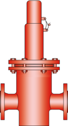
The PROTEGO® in-line valve DV/ZW-F is a state-of-the-art pressure and vacuum relief valve with flanged connections for use in a vent line. Typically, the valve is installed in the inbreathing and out-breathing lines of tanks, vessels, and process equipment to protect against unallowable overpressure and underpressure.
The valve prevents emission losses almost up to the set pressure and prevents air intake almost up to set vacuum. It is designed in a way that if the set pressure is exceeded, the vapors are released into an exhaust pipe (e.g., vent header). If the set vacuum is exceeded, atmospheric air is pulled into the system. For structural reasons, the vacuum valve pallet is one size smaller than the pressure valve pallet. Due to the springloaded design, higher set pressures can be achieved.
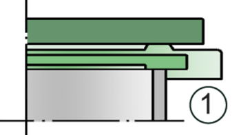
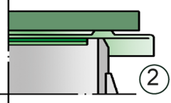
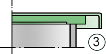
The device will start to open as soon as the set pressure is reached and only requires 10% overpressure to full lift. Continuous investments in and a commitment to research and development have allowed PROTEGO® to develop a low pressure valve which has the same opening characteristic as a high pressure safety relief valve. This “full lift type” technology allows the valve to be set at just 10% below the maximum allowable working pressure or vacuum (MAWP or MAWV) of the tank and still safely vent the required mass flow. The inbreathing will start as soon as the differential pressure between the atmospheric pressure and the tank is greater than the set pressure of the vacuum valve pallet. The tank pressure is maintained up to set pressure with a tightness that is above the normal standards due to our highly developed manufacturing technology. This feature is ensured by valve seats made of high quality stainless steel and with individually lapped valve pallets (1), (3), or with an air cushion seal (2), in conjunction with a high quality FEP diaphragm and a sturdy housing design. After the overpressure is released or the vacuum is balanced, the valve re-seats and provides a tight seal. The optimized fluid dynamic design of the valve body and valve pallet is a result of many years of research, resulting in stable operation of the valve pallet, optimized performance, and reduced product losses.
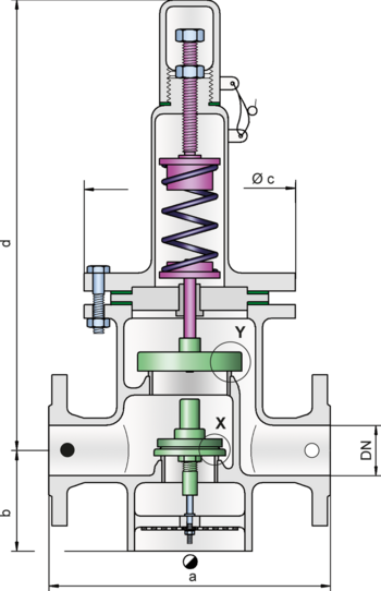
Dimensions
To select the nominal size (DN), please use the flow capacity charts on the following pages
| DN | 40 / 1½“ | 50 / 2" | 80 / 3" | 100 / 4" | 150 / 6" |
| a | 280 / 11.02 | 280 / 11.02 | 340 / 13.39 | 390 / 15.35 | 520 / 20.47 |
| b | 85 / 3.35 | 85 / 3.35 | 125 / 4.92 | 140 / 5.51 | 185 / 7.28 |
| c | 210 / 8.27 | 210 / 8.27 | 280 / 11.02 | 310 / 12.20 | 390 / 15.35 |
| d | 565 / 22.24 | 565 / 22.24 | 675 / 26.57 | 805 / 31.69 | 1070 / 42.13 |
Material selection for housing
| Design | A | B |
| Housing | Steel | Stainless Steel |
| Heating jacket (DV / ZW-F-H-...) | Steel | Stainless Steel |
| Valve seat | Stainless Steel | Stainless Steel |
| Gasket | PTFE | PTFE |
Material selection for pressure valve pallet
| Design | A |
| Pressure range [mbar] [inch W.C.] | >+60 up to +500 >+24 up to +200 |
| Valve pallet | Stainless Steel |
| Sealing | Metal to Metal |
| Spring | Stainless Steel |
Material selection for vacuum valve pallet
| Design | A* | B* | C | D |
| Pressure range [mbar] [inch W.C.] | -3,5 up to -5,0 -1.4 up to -2.0 | <-5,0 up to -14 <-2.0 up to -5.6 | <-14 up to -35 <-5.6 up to -14 | <-35 up to -50 <-14 up to -20 |
| Valve pallet | Aluminium | Stainless Steel | Stainless Steel | Stainless Steel |
| Sealing | FEP | FEP | Metal to Metal | Metal to Metal |
Flange connection type
| EN 1092-1; Form B1 |
| ASME B16.5 CL 150 R.F. |
Design Types and Specifications
The pressure valve pallet is spring loaded, the vacuum valve pallet weight loaded. Lower set pressures for the pressure side are achieved through weight loaded type DV/ZW.
Two different designs are available:
In-line pressure and vacuum relief valve, standard design | DV/ZW-F – |
In-line pressure and vacuum relief valve with heating jacket | DV/ZW-F - H |
Additional special devices available upon request
Within piping systems the influence of backpressure has to be considered in deciding the set pressure and opening characteristics. For special design solutions (e.g. partial load operation) the valve can be supplied with standard valve pallets (with proportional opening function).
Settings
| Pressure: | +60 mbar | +500 mbar | |
| +24 inch W.C. | +200 inch W.C. | ||
| Vacuum: | -3.5 mbar | -50 mbar | |
| -1.4 inch W.C. | -20 inch W.C. | ||
| Vacuum: | -3.5 mbar | -14 mbar | |
| -1.4 inch W.C. | -5.6 inch W.C. | ||
| by set pressure up to +150 mbar / +60 inch W.C. | |||
Higher set pressure and lower set vacuum upon request.
Flow Capacity Chart
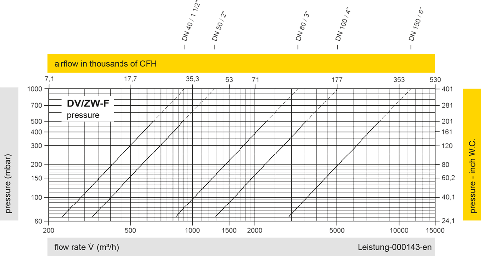
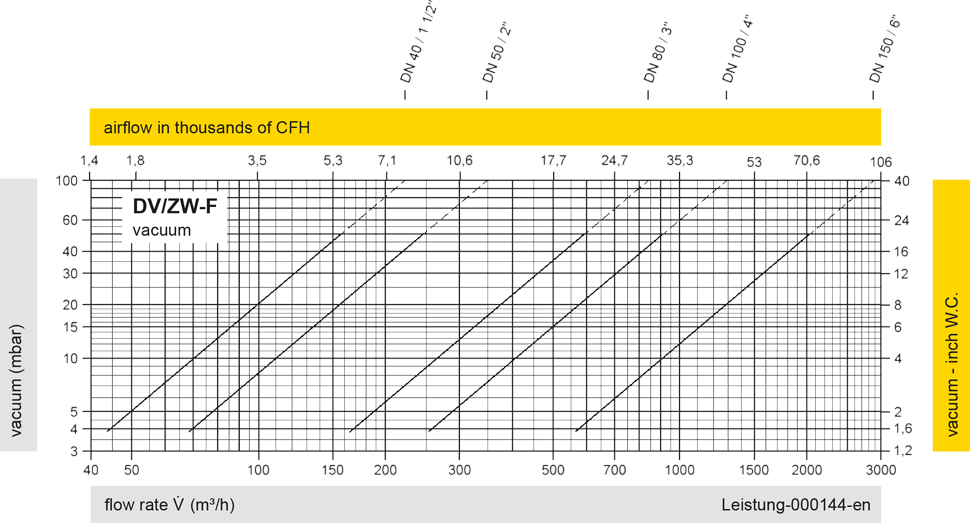
The flow capacity charts have been determined with a calibrated and TÜV certified flow capacity test rig. Volume flow V in (m³/h) and CFH refer to the standard reference conditions of air ISO 6358 (20°C, 1bar). For conversion to other densities and temperatures refer to Sec. 1: “Technical Fundamentals”.