PV/EBR
Pressure/Vacuum Relief Valve deflagration- and endurance burning-proof
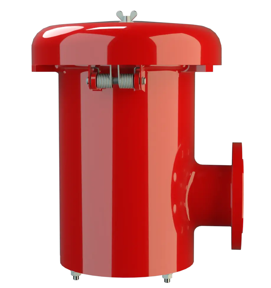
Caractéristiques
Fonction et description
Combined Pressure and Vacuum Relief Valve
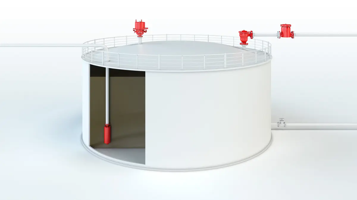
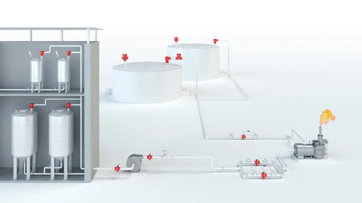
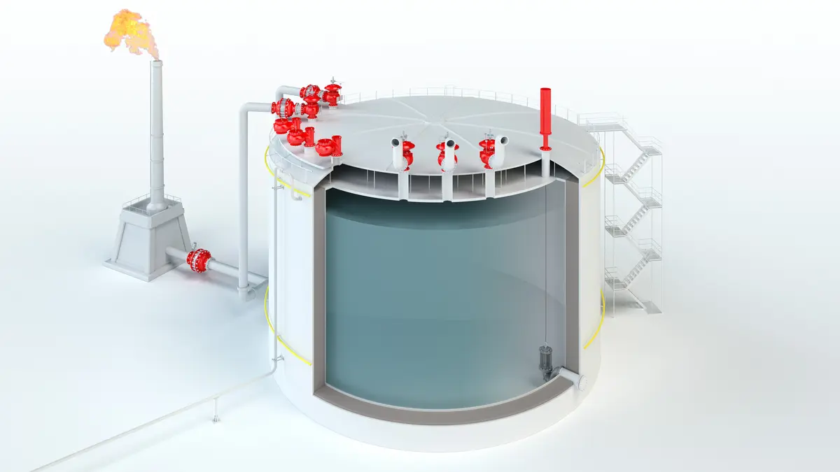
The Deflagration Deflagration Explosion propagating at subsonic velocity. -Proof and Endurance-Burning-Proof PV/EBR Type PROTEGO® valve is a highly developed combined pressure Pressure (gauge pressure) Pressure for which the value is equal to the algebraic difference between the absolute pressure and the atmospheric pressure. / vacuum relief valve Vacuum relief valve A vacuum relief valve is used to ventilate a part of the system and protects it from impermissible underpressure. for high flow capacities with an integrated Flame Arrester Flame arrester Device fitted to the opening of an enclosure, or to the connecting pipe work of a system of enclosures, and whose intended function is to allow flow but prevent the transmission of a flame. . It is primarily used as a device Device A device is a pipe component that influences the media flow by opening, closing, or partially shutting off the flow channel or by dividing or mixing the media flow. for flame transmission-proof Flame transmission-proof Characteristic of a device to avoid flashback. in-breathing and out-breathing on tanks, containers, and process equipment Equipment Machines, appliances, fixed or mobile devices, control parts and accessories, and warning and prevention systems, whether separate or combined, intended for the generation, transfer, storage, measurement, control, and conversion of energy, and for the processing of materials, which have their own potential source of ignition and may cause an explosion. . The valve offers reliable protection against overpressure Overpressure Overpressure refers to an increase in pressure in a system or vessel above the normal operating pressure. and vacuum Vacuum Vacuum is the pressure in an enclosed space that is lower than the ambient pressure. , prevents the in-breathing of air and product Product Includes equipment, protective systems, devices, components and combinations of these. losses almost up to the set pressure Set pressure Set pressure is the gauge pressure at the device inlet at which the relief device is set to start opening under service conditions. , and protects against atmospheric deflagration and endurance burning Endurance burning Stabilized burning for an unlimited time. if stabilized burning Stabilized burning Steady burning of a flame stabilized at, or close to the flame arrester element. occurs.

For Explosion Groups IIA to IIB3
The PROTEGO® Flame Arrester Unit PROTEGO® flame arrester unit The PROTEGO® flame arrester unit is the main component of a flame arrester. It prevents flame propagation. is designed to achieve minimum pressure drop with maximum safety. PROTEGO® PV/EBR valves are available for substances from explosion Explosion Abrupt oxidation or decomposition reaction producing an increase in temperature, pressure, or in both simultaneously. groups IIA to IIB3 (NEC group D to C MESG ≥ 0.65 mm). The valve functions proportional, so the set pressures should be selected in relation to the proportional behavior (such as a 10%, 40%, or 100% overpressure from the set pressure to the relieving pressure Relieving pressure The relieving pressure is the vacuum or overpressure at which the valve reaches the lift required for the mass flow to be discharged. at which the required flow performance is reached).
Advanced Manufacturing Technology
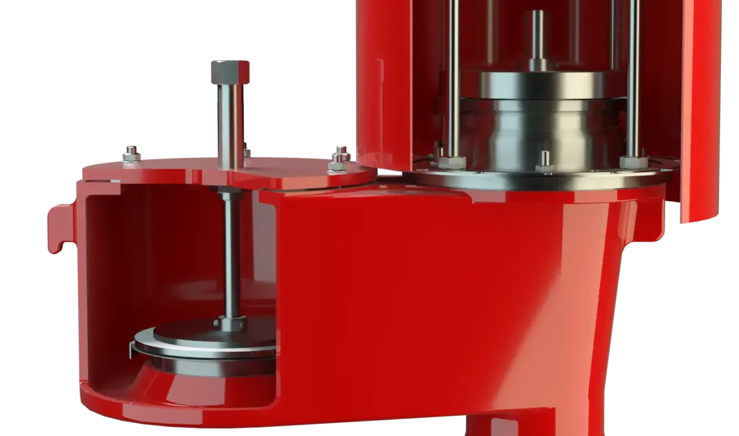
The tank pressure Tank pressure Tank pressure is the pressure within a tank. is maintained up to the set pressure with a tightness that is above the normal standards due to our state-of-the-art manufacturing technology. This feature is ensured by the valve seats made of high quality stainless steel and with individually lapped valve pallets (1), or with an air cushion seal Seal A seal prevents or limits unwanted transfer of product from one container to another. Seal is used as superordinate term for all types of sealing elements. (2), in conjunction with high quality FEP diaphragm Diaphragm A diaphragm is a thin layer of material, which has a large surface area. . The valve pallets are also available with a PTFE seal to prevent the valve pallets from sticking when sticky substances are used and to enable the use of corrosive fluids. After the overpressure is released, the valve re-seats and provides a tight seal.

Main Component – PROTEGO® Flame Arrester Unit
If the set pressure is exceeded, explosive gas/product vapor/air mixtures are released into the atmosphere. If this mixture ignites, the integrated PROTEGO® Flame Arrester Unit (3) prevents flame transmission into the tank. If additional mixture continues to flow and stabilized burning occurs, the integrated Flame Arrester Unit prevents flashback Flashback Phenomenon occurring in a flammable mixture of air and gas when the local velocity of the combustible mixture becomes less than the flame velocity, causing the flame to travel back to the point of mixture. as a result of endurance burning. The valve is protected and also fulfils its function under these severe conditions. The spring Spring A spring is a spiral of wire which returns to its original shape after it is pressed or pulled. -loaded weather hood Weather hood A weather hood is a cover to protect the internal components of a device from environmental influences. opens as soon as the melting element Melting element The melting element is a component that consists of a housing with a lower and upper part. (4) melts.

Many Individual Certifications
The valve can be used at an operating temperature Operating temperature Temperature reached when the equipment is operating under design conditions. of up to +60°C / 140°F and meets the requirements of European Tank Design Standard EN 14015 (Appendix L) and ISO 28300 (API 2000). EU conformity according to the currently valid ATEX directive. Approvals according to other national/international regulations on request.
Dimensions
To select the nominal size Nominal size The nominal size is an alphanumeric designation of size for components in a piping system, used for reference purposes, comprising the letters DN followed by a dimensionless integer that is indirectly related to the physical size of the bore or outside diameter of the connections, expessed in millimeters. (DN), please use the flow capacity charts on the following pages
| DN | 80 / 3" | 80 / 3" | 100 / 4" | 100 / 4" | |
| Set pressure | ≤ +35 mbar | > +35 mbar | ≤ +35 mbar | > +35 mbar | |
| Set pressure | ≤ +14 inch W.C. | > +14 inch W.C. | ≤ +14 inch W.C. | > +14 inch W.C. | |
| a | 345 / 13.58 | 475 / 18.70 | 345 / 13.58 | 475 / 18.70 | |
| b | 141 / 5.55 | 141 / 5.55 | 141 / 5.55 | 141 / 5.55 | |
| c | 218 / 8.58 | 218 / 8.58 | 218 / 8.58 | 218 / 8.58 | |
| d | 353 / 13.90 | 353 / 13.90 | 353 / 13.90 | 353 / 13.90 |
Dimensions in mm / inches
Dimensions for pressure/ vacuum relief valve with heating jacket upon request
Material selection for housing
| Design | B | C |
| Housing Housing A housing is a solid shell, which surrounds a content, either protecting the content from external influences, or protecting the environment from the content. | Steel | Stainless Steel |
| Heating jacket (PV / EBR-H-...) | Steel | Stainless Steel |
| Valve seat Valve seat The valve seat is a component on which the valve pallet rests when the valve is closed. | Stainless Steel | Stainless Steel |
| Weather hood | Steel | Stainless Steel |
Special materials upon request
Material combinations of flame arrester unit
| Design | A |
| FLAMEFILTER® cage | Stainless Steel |
| FLAMEFILTER® | Stainless Steel |
| Spacer Spacer The spacer is a component that is generally used in a PROTEGO® flame arrester as a spacer within the FLAMEFILTER® set. | Stainless Steel |
Special materials upon request
Material selection for pressure valve pallet
| Design | A | B | C | D |
| Presure range [mbar] [inch W.C.] | +2,0 up to +3,5 +0.8 up to 1.4 | >+3,5 up to +14 >+1.4 up to +5.6 | >+14 up to +210 >+5.6 up to +84 | >+35 up to +210 >+14 up to 84 |
| Valve pallet Valve pallet Valve pallet is the generic term for the assembly that rests on the valve seat. | Aluminium | Stainless Steel | Stainless Steel | Stainless Steel |
| Sealing | FEP | FEP | Metal to Metal | PTFE |
Special material as well as higher set pressure upon request
Material selection for vacuum valve pallet
| Design | A | B | C | D |
| Vacuum range [mbar] [inch W.C.] | -3.5 up to -5.0 -1.4 up to -2.0 | <-5.0 up to -14 <-2.0 up to -5.6 | <-14 up to -50 <-5.6 up to -20 | <-14 up to -50 <-5.6 up to -20 |
| Valve pallet | Aluminium | Stainless Steel | Stainless Steel | Stainless Steel |
| Sealing | FEP | FEP | Metal to Metal | PTFE |
Special material as well as higher set vacuum Set vacuum Internal negative gauge pressure at which a vacuum valve first opens. upon request
Selection of explosion group
| MESG | Expl. Gr. (IEC / CEN) | Gas Group (NEC) |
| > 0,90 mm | IIA | D |
| ≥ 0,65 mm | IIB3 | C |
Special approvals upon request
Flange connection type
| EN 1092-1; Form B1 |
| ASME B16.5 CL 150 R.F. |
other types upon request
Design Types and Specifications
Almost any combination of vacuum and pressure levels can be set for the valve. The valve discs are weight loaded. When the difference between the pressure and vacuum exceeds 150 mbar / 60.2 inch W.C., special valve discs are used.There are two different designs:
Additional special devices available upon request
Settings
| Pressure: | +2.0 mbar | +210 mbar |
| +0.8 inch W.C. | +84 inch W.C. | |
| Vacuum: | -14 mbar | -50 mbar |
| -5.6 inch W.C. | -20 inch W.C. | |
| Vacuum: | -3.5 mbar | -14 mbar |
| -1.4 inch W.C. | -5.6 inch W.C. |
for presssure up to max. + 150 mbar / 60.2 inch W.C.
Higher and lower settings upon request
Flow Capacity Chart
The flow capacity charts have been determined with a calibrated and TÜV certified flow capacity test rig. Volume flow V in (m³/h) and CFH refer to the standard reference conditions of air ISO 6358 (20°C, 1bar). For conversion to other densities and temperatures refer to Sec. 1: “Technical Fundamentals”.