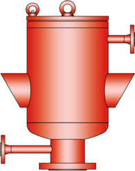
SV/T-0-H
Vacuum Relief Valve in a special heat jacketed design
- excellent tightness resulting in lowest possible product losses and reduced environmental pollution
- high flow capacity
- valve pallet is guided inside the housing to protect against harsh weather conditions
- can be used in explosion hazardous areas
- complete heating jacket up to the flange to avoid ice build-up
- maximum allowable heating medium temperature of 320°C / 608°F (at 6 bar/87 psi)
- a special design that preheats incoming air is also available
- available in a special design with a heatable valve cover
- a valve pallet cover prevents the adjustment of the set pressure due to dust deposits or condensate
- sturdy housing design
- available in a special design with lifting device
Función y Descripción
The SV/T-0-H type PROTEGO® valve is a highly developed vacuum relief valve with a valve housing that is equipped with a heating jacket that can be heated up to the flange. It is primarily used as a device for in-breathing in tanks, containers, and process engineering equipment under difficult operating conditions. This includes extreme weather conditions or products that tend to form polymers at certain temperatures, stick together, or form deposits that negatively influence function (such as bitumen, tar, dust). The valve offers reliable protection against vacuum and prevents air intake almost up to the set vacuum.
When the set vacuum is reached, the valve starts to open and reaches full lift within a 40% vacuum increase. Up to the set vacuum, the tank vacuum is maintained with a seal that is far superior to the conventional standard due to the highly developed manufacturing technology. This feature is achieved by valve seats made of high quality stainless steel with precisely lapped valve pallets and a sturdy housing design. After the vacuum is released, the valve re-seats and again provides a tight seal.
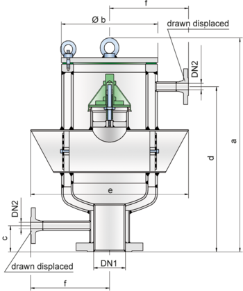
Dimensiones
To select the nominal size (DN), use the flow capacity chart on the following page
| DN1 | 80* / 3"* | 100 / 4" | 150 / 6" | 200 / 8" | 250 / 10" |
| DN2 | 15 / ½" | 15 / ½" | 15 / ½" | 15 / ½" | 15 / ½" |
| a | 570 / 22.44 | 570 / 22.44 | 720 / 28.35 | 920 / 36.22 | 1050 / 41.34 |
| b | 275 / 10.83 | 275 / 10.83 | 355 / 13.98 | 405 / 15.94 | 508 / 20.00 |
| c | 70 / 2.76 | 70 / 2.76 | 60 / 2.36 | 70 / 2.76 | 70 / 2.76 |
| d | 440 / 17.32 | 440 / 17.32 | 590 / 23.23 | 790 / 31.10 | 920 / 36.22 |
| e | 450 / 17.72 | 450 / 17.72 | 650 / 25.59 | 750 / 29.53 | 950 / 37.40 |
| f | 225 / 8.86 | 225 / 8.86 | 260 / 10.24 | 300 / 11.91 | 350 / 13.78 |
Selección de materiales para la vivienda
| Design | A | B |
| Housing | Steel | Stainless Steel |
| Heating jacket | Steel | Stainless Steel |
| Valve seat | Stainless Steel | Stainless Steel |
| Sealing | PTFE | PTFE |
Selección de materiales para la válvula de vacío
| Design | A | B | C |
| Vacuum range [mbar] [inch W.C.] | -7,0 up to -25 -2.8 up to -10 | -10 up to-30 -4.0 up to -12 | -30 up to-50 -12 up to -20 |
| Valve pallet | Aluminium | Stainless Steel | Stainless Steel |
| Valve pallet hood | Stainless Steel | Stainless Steel | Stainless Steel |
| Sealing | Metal to Metal | Metal to Metal | Metal to Metal |
Tipo de bridas de conexión
| EN 1092-1; Form B1 |
| ASME B16.5 CL 150 R.F. |
Modelo y especificación
The valve pallet is weight-loaded.
Vacuum valve in basic design with heating jacket | SV/T - 0 - H |
Additional special devices available upon request.
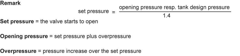
Settings
| Vacuum: | -7 mbar | -50 mbar | |
| -2.8 inch W.C. | -20 inch W.C. |
Diagrama de flujo volumétrico
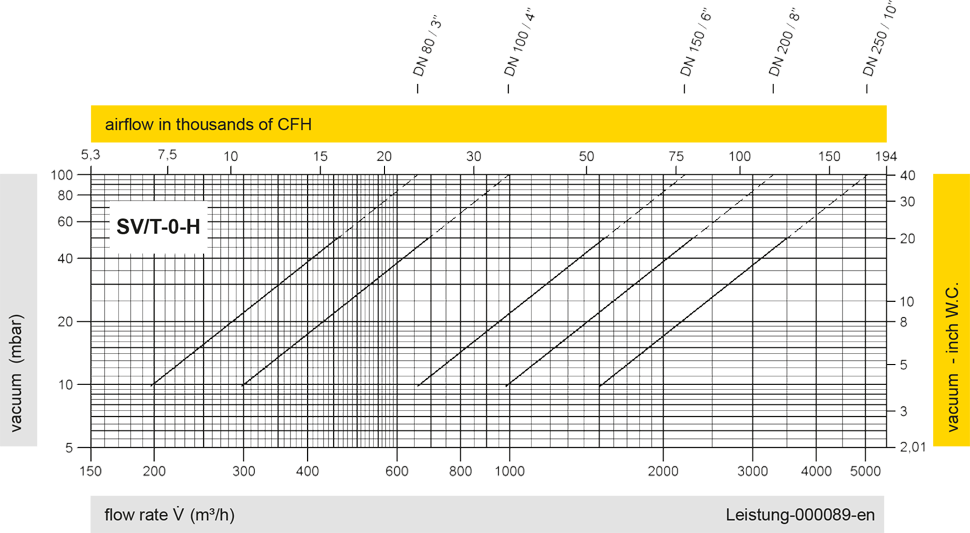
Los diagramas de flujo volumétrico han sido determinados con un banco de pruebas de caudal calibrado y certifi - cado por TÜV. El flujo volumétrico V. en [m³/h] y el CFH se refi eren a las condiciones estándar de referencia de aire según ISO 6358 (20°C, 1bar). La conversión a otras densidades y temperaturas están referidas en el Vol. 1: “Fundamentos Técnicos”.