P/EB-E
Pressure Relief Valve deflagration- and endurance burning-proof
- extreme tightness, resulting in lowest possible product losses and reduced environmental pollution
- set pressure close to opening pressure for optimum pressure maintenance in the system
- valve opens later and closes earlier than conventional valves
- valve pallet is guided inside the housing to protect against harsh weather conditions
- can be used as protective system according in areas with potentially explosive atmospheres in accordance with ATEX
- protected against deflagration and endurance burning of alcohol/air mixtures from explosion group IIB1
- PROTEGO® flame arrester unit provides protection against atmospheric deflagrations and endurance burning
- integrated PROTEGO® flame arrester unit saves space and weight and reduces costs
- flame arrester unit is protected from clogging and sticky substances caused by product vapors
- minimum pressure loss of the PROTEGO® flame arrester unit
- flameproof condensate drain
- maintenance-friendly design
- modular design enables replacement of individual FLAMEFILTER® discs and valve pallet
Función y Descripción
The deflagration-proof and endurance burning-proof P/EB-E type PROTEGO® valve is a highly developed pressure relief valve for large flows with an integrated flame arrester unit that is specifically designed for use in ethanol production, processing, and storage. It is primarily used as a device for flame transmission-proof out-breathing on tanks, containers, and process equipment. The valve offers reliable protection against overpressure and prevents product losses almost up to the set pressure, while at the same time protecting against atmospheric deflagration and endurance burning if stabilized burning occurs. The PROTEGO® flame arrester unit is designed to achieve minimum pressure drop with maximum safety. The P/EB-E valve is available for substances of explosion group IIB1 (MESG ≥ 0.85 mm) and provides specific protection against deflagration and endurance burning of alcohol/air mixtures (such as ethanol/air).
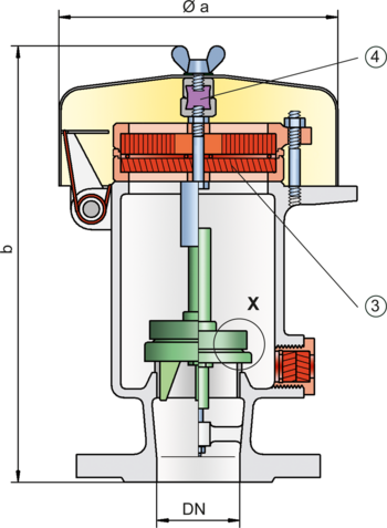
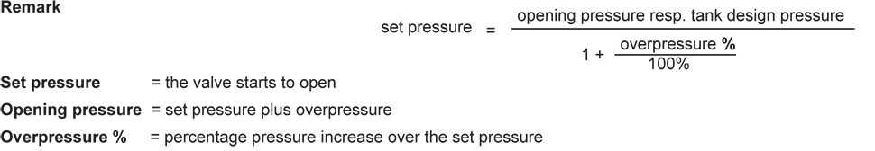
The valve functions proportional, so the set pressures should be selected in relation to the proportional behavior (such as a 10%, 40%, or 100% overpressure from the set pressure to the relieving pressure at which the required flow performance is reached). The tank pressure is maintained up to the set pressure with a tightness that is far above the usual standards due to our state-of-the-art manufacturing. This feature is ensured by the valve seats made of high quality stainless steel and with individually lapped valve pallets (1), or with an air cushion seal (2), in conjunction with high quality FEP diaphragm. The valve pallets are also available with a PTFE seal to prevent the valve pallets from sticking when sticky substances are used and to enable the use of corrosive fluids. After the overpressure is released, the valve re-seats and provides a tight seal.
If the set pressure is exceeded, explosive gas/product vapor/air mixtures are released into the atmosphere. If this mixture ignites, the integrated PROTEGO® flame arrester unit (3) prevents flame transmission into the tank. If additional mixture continues to flow and stabilized burning occurs, the integrated flame arrester unit prevents flashback as a result of endurance burning. The valve is protected and also fulfils its function under these severe conditions. The spring-loaded weather hood pens as soon as the melting element (4) melts.
The valve can be used up to an operating temperature of up to +60°C / 140°F and meets the requirements of European tank design standard EN 14015 (Appendix L) and ISO 28300 (API 2000).
EU conformity according to the currently valid ATEX directive. Approvals according to other national/international regulations on request.
Dimensiones
To select the nominal size (DN), please use the flow capacity chart on the following page
| DN | 50 / 2" | 50 / 2" | 80 / 3" | 80 / 3" |
| Set pressure | ≤ +80 mbar | > +80 mbar | ≤ +80 mbar | > +80 mbar |
| Set pressure | ≤ +32.1 inch W.C. | > +32.1 inch W.C. | ≤ +32.1 inch W.C. | > +32.1 inch W.C. |
| a | 218 / 8.58 | 218 / 8.58 | 218 / 8.58 | 218 / 8.58 |
| b | 288 / 11.34 | 453 / 17.83 | 290 / 11.42 | 455 / 17.91 |
Selección de materiales para la vivienda
| Design | B | C |
| Housing | Steel | Stainless Steel |
| Heating jacket (P / EB-E-H-...) | Steel | Stainless Steel |
| Valve seat | Stainless Steel | Stainless Steel |
| Weather hood | Steel | Stainless Steel |
Combinación de materiales para la unidad apagallamas
| Design | A |
| FLAMEFILTER® cage | Stainless Steel |
| FLAMEFILTER® | Stainless Steel |
| Spacer | Stainless Steel |
Material selection for valve pallet
| Design | A | B | C | D |
| Pressure range [mbar] [inch W.C.] | +3.5 up to +5.0 +1.4 up to +2.0 | >+5.0 up to +14 >+2.0 up to +5.6 | >+14 up to +210 >+5.6 up to +84 | >+14 up to +210 >+5.6 up to +84 |
| Valve pallet | Aluminium | Stainless Steel | Stainless Steel | Stainless Steel |
| Sealing | FEP | FEP | Metal to Metal | PTFE |
Selección del grupo de explosión
| MESG | Expl. Gr. (IEC / CEN) | Gas Group (NEC) |
| ≥ 0,85 mm | IIB1 | – |
Tipo de bridas de conexión
| EN 1092-1; Form B1 |
| ASME B16.5 CL 150 R.F. |
Modelo y especificación
The valve disc is weight-loaded. At set pressure >80 mbar (32.1 inch W.C.), an elongated design is used
There are two different designs:
Pressure relief valve, basic design | P/EB - E - – |
Pressure relief valve with heating jacket (max. heating fluid temperature +85°C / 185°F) | P/EB - E - H |
Additional special devices available upon request
Settings
| Pressure: | +3.5 mbar | +210 mbar | |
| +1.4 inch W.C. | +84 inch W.C. |
Diagrama de flujo volumétrico
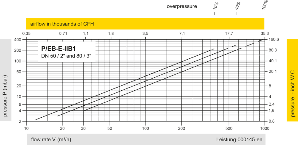
Los diagramas de flujo volumétrico han sido determinados con un banco de pruebas de caudal calibrado y certifi - cado por TÜV. El flujo volumétrico V. en [m³/h] y el CFH se refi eren a las condiciones estándar de referencia de aire según ISO 6358 (20°C, 1bar). La conversión a otras densidades y temperaturas están referidas en el Vol. 1: “Fundamentos Técnicos”.