FA-I-PTFE
In-Line Deflagration Flame Arrester concentric design, bidirectional
- build up of adhesive materials is prevented by the smooth surfaces
- application especially for corrosive and polymerizing media
- minimum number of FLAMEFILTER® discs due to patented design
- service-friendly design
- the modular design enables each individual FLAMEFILTER® to be replaced
- bidirectional operation as well as any direction of flow
- installation of temperature sensors is possible
- less soiling of the device lowers service, operating and life-cycle costs
- minimum pressure loss and associated low operating and life-cycle costs
Función y Descripción
The in-line deflagration flame arresters type PROTEGO® FA-I-PTFE are the latest generation of flame arresters and are distinguished by their unique resistance to adhesive and corrosive media. The use of fluoroplastics as a high-tech housing coating and as solid material for the flame arrester element is unique throughout the world.
When installing the deflagration flame arrester make sure that the distance between potential ignition sources and the location of the installed device, the L/D ratio (pipe length/pipe diameter), does not exceed the value of 50.
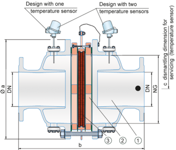
The deflagration flame arrester is symmetrical and offers bidirectional flame transmission protection. The arrester essentially consists of two coated housing parts (1) and the PROTEGO® flame arrester unit (2) in the center. The PROTEGO® flame arrester unit is modular and consists of several FLAMEFILTER® discs (3) and spacers firmly held in a FLAMEFILTER® casing. The number of PTFE-FLAMEFILTER® discs and their gap size depends on the arrester‘s conditions of use.
The deflagration flame arrester PROTEGO® FA-I-PTFE can be used for explosion group IIA (NEC group D). The standard design is approved at an operating temperature up to +60°C / 140°F. The maximum allowable operating pressure depends on nominal diameter (DN) and nominal size (NG) and amounts to a maximum of 1.6 bar / 23.2 psi absolute (for DN 100 / 4” and DN 150 / 6” see table 3).
EU conformity according to the currently valid ATEX directive. Approvals according to other national/international regulations on request.
Dimensiones
To select series and nominal size (DN) - nominal width (NG) combination, please use the flow capacity chart on the following page
| DN | 50 / 2" | 80 / 3" | 100 / 4" | 150 / 6" |
| NG | 150 / 6" | 150 / 6" | 200 / 8" | 300 / 12" |
| a | 287 / 11.30 | 287 / 11.30 | 342 / 13.46 | 447 / 17.60 |
| b | 380 / 14.96 | 380 / 14.96 | 468 / 18.43 | 612 / 24.09 |
| c | 430 / 16.93 | 430 / 16.93 | 480 / 18.90 | 530 / 20.87 |
Material for housing
| Design | A |
| Housing | Steel with an ECTFE coating |
| Gasket | PTFE |
| Flame arrester unit | A, B, C |
Combinación de materiales para la unidad apagallamas
| Design | A | B | C |
| FLAMEFILTER® cage | Steel with an ECTFE coating | Hastelloy | Stainless Steel |
| Spider rings | Steel with an ECTFE coating | Hastelloy | Stainless Steel |
| FLAMEFILTER®* | PTFE* | PTFE* | PTFE* |
| Spacer | PEEK / ETFE / FEP | PEEK / ETFE / FEP | PEEK / ETFE / FEP |
Selección del grupo de explosión
| MESG | Expl. Gr. (IEC / CEN) | Gas Group (NEC) |
| > 0.90 mm | IIA | D |
Selección de la máxima presión de operación
| DN | 50 / 2" | 80 / 3" | 100 / 4" | 150 / 6" |
| NG | 150 / 6" | 150 / 6" | 200 / 8" | 300 / 12" |
| Pmax | 1.6 / 23.2 | 1.6 / 23.3 | 1.2 / 17.4 | 1.2 / 17.4 |
Especificación de la máx. temperatura de operación
| ≤ 60°C / 140°F | Tmaximum allowable operating temperature in °C |
| - | Designation |
Tipo de bridas de conexión
| EN 1092-1; Form B1 |
| ASME B16.5 CL 150 R.F. |
Modelo y especificación
There are three different designs:
Basic in-line deflagration flame arrester | FA-I - PTFE – |
In-line deflagration flame arrester with integrated temperature sensor* as additional protection against short-time burning from one side | FA-I - PTFE - T |
In-line deflagration flame arrester with two integrated temperature sensors* for additional protection against short-time burning from both sides | FA-I - PTFE - TB |
Additional special devices available upon request
*Resistance thermometer for device group II, category (1) 2 (GII cat. (1) 2)
Diagrama de flujo volumétrico
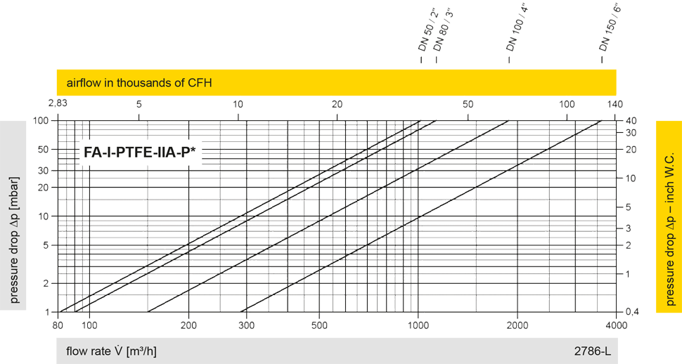
Los diagramas de flujo volumétrico han sido determinados con un banco de pruebas de caudal calibrado y certifi - cado por TÜV. El flujo volumétrico V. en [m³/h] y el CFH se refi eren a las condiciones estándar de referencia de aire según ISO 6358 (20°C, 1bar). La conversión a otras densidades y temperaturas están referidas en el Vol. 1: “Fundamentos Técnicos”.