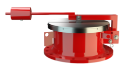
ER/VH
Pressure Relief Valve
- 10% technology for minimum pressure increase up to full lift
- excellent tightness resulting in lowest possible product losses and reduced environmental pollution
- set pressure close to opening pressure for optimum pressure maintenance in the system
- high flow capacity
- can be used in explosion hazardous areas
- sturdy housing design
- secured housing cover with lever and lockable weight load
- best technology for API tanks
Función y Descripción
The ER/VH type PROTEGO® valve is a highly developed emergency pressure relief valve with high flow capacity. It is primarily used as a device for emergency pressure relief for storage tanks, containers, silos, and process engineering equipment. It offers reliable protection against overpressure and prevents excessive product vapor loss close to the set pressure. It is designed to release particularly large amounts to prevent the vessel from rupturing in an emergency case. Higher set pressures are achieved by a lever with a lockable weight load. The position of the weight is set at the factory. Starting at DN 500, the devices can also be used as manhole covers.
When the set pressure is reached, the valve starts to open and is fully open within 10% overpressure. This unique 10% ”full lift type technology” enables a pressure setting that is only 10% below the maximum allowable working pressure or design pressure of the tank.
Even in the low pressure range, the vent has the opening characteristic comparable to a typical high pressure safety relief valve. The full lift type pallets are a result of many years of development. The valve pallet is mounted on one side.
Due to the highly developed manufacturing technology, the tank pressure is maintained up to the set pressure with a tightness that is far superior to the conventional standard. This feature is achieved by valve seats made of stainless steel with an inserted O-ring seal, a precisely lapped valve pallet, and a sturdy housing design. After the excess pressure is released, the valve re-seats and provides a tight seal again.
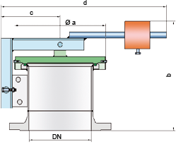
Dimensiones
To select the nominal size (DN), use the flow capacity chart on the following page
| DN | 200 / 8" | 250 / 10" | 300 / 12" | 350 / 14" | 400 / 16" | 450 / 18" | 500 / 20" | 600 / 24" | 700 / 28" |
| a | 305 / 12.01 | 375 / 14.76 | 425 / 16.73 | 445 / 17.52 | 495 / 19.49 | 545 / 21.46 | 615 / 24.21 | 715 / 28.15 | 795 / 31.30 |
| b | 350 / 13.78 | 365 / 14.37 | 385 / 15.16 | 390 / 15.35 | 390 / 15.35 | 415 / 16.34 | 430 / 16.93 | 450 / 17.72 | 465 / 18.31 |
| c | 200 / 7.87 | 240 / 9.45 | 265 / 10.43 | 285 / 11.22 | 310 / 12.20 | 330 / 12.99 | 360 / 14.17 | 410 / 16.14 | 450 / 17.72 |
| d | 590 / 23.23 | 735 / 28.94 | 780 / 30.71 | 845 / 33.27 | 890 / 35.04 | 1070 / 42.13 | 1090 / 42.91 | 1140 / 44.88 | 1380 / 54.33 |
Selección de materiales
| Design | A | B |
| Housing | Steel | Stainless Steel |
| Valve seat | Stainless Steel | Stainless Steel |
| Valve pallet | Stainless Steel or Steel-Stainless Steel | Stainless Steel |
| Sealing | FPM | FPM |
| Weight | Steel | Stainless Steel |
Tipo de bridas de conexión
| EN 1092-1; Form B1 |
| ASME B16.5 CL 150 R.F. |
Modelo y especificación
The valve pallet is weight-loaded. Lower pressures are generally achieved without a lever design (see ER-V-LP, ER/V), and higher pressures are realized with spring-loading (see ER/V-F).
Pressure valve in basic design | ER/VH |
Additional special devices available upon request.
Settings
| DN 200 to DN 350 | >+40 mbar | +60 mbar | |
| >+16 inch W.C. | +24 inch W.C. | ||
| DN 400 to DN 700 | >+25 mbar | +60 mbar | |
| >+10 inch W.C. | +24 inch W.C. |
Diagrama de flujo volumétrico
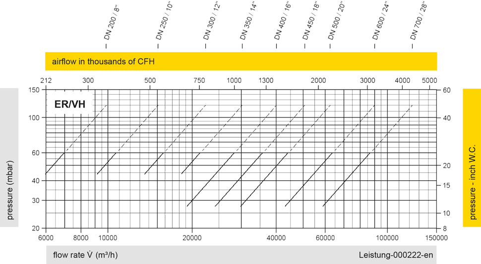
Los diagramas de flujo volumétrico han sido determinados con un banco de pruebas de caudal calibrado y certifi - cado por TÜV. El flujo volumétrico V. en [m³/h] y el CFH se refi eren a las condiciones estándar de referencia de aire según ISO 6358 (20°C, 1bar). La conversión a otras densidades y temperaturas están referidas en el Vol. 1: “Fundamentos Técnicos”.