DA-E
Eccentric In-Line Detonation Flame Arrester for stable detonations and deflagrations in a straight through design, bidirectional
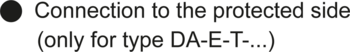
- eccentric design prevents condensate build-up
- modular design enables replacement of the individual FLAMEFILTER® discs
- easy maintenance with fast assembly and disassembly of the FLAMEFILTER®
- advanced design allows for installation close to ground level
- bi-directional operation, as well as any flow direction and installation position
- provides protection against deflagration and stable detonation
- installation of temperature sensors possible
- cost-effective spare parts
Función y Descripción
The PROTEGO® DA-E series of detonation arresters are distinguished by its eccentric housing shape. When condensate accumulates within the PROTEGO® flame arrester unit, the design allows the liquid to drain without collecting large amounts in the housing. The eccentric design of the device has distinctive advantages over the classic flame arresters when installed at lower depths.
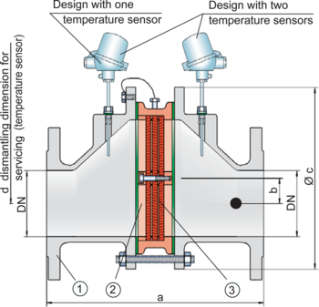
The detonation arrester is symmetrical and offers bi-directional flame arresting. The arrester essentially consists of two housing parts (1) and the PROTEGO® flame arrester unit (2) in the center. The PROTEGO® flame arrester unit consists of several FLAMEFILTER® discs (3) and spacers firmly held in a FLAMEFILTER® casing. The number of FLAMEFILTER® discs and their gap size depends on the arrester‘s intended use. By specifying the operating conditions, such as the temperature, pressure, explosion group, and the composition of the fluid, the optimum detonation arrester can be selected. The PROTEGO® DA-E series of flame arresters are available for explosion groups IIA to IIB3 (NEC Group D to C MESG ≥ 0.65 mm).
The standard design can be used with an operating temperature of up to +60°C / 140°F and an absolute operating pressure acc. to table 3. Devices with special approval for higher pressures and higher temperatures are available upon request.
Type-approved in accordance with the current ATEX Directive and EN ISO 16852, as well as other international standards.
Dimensiones
To select the nominal size (DN), please use the flow capacity charts on the following pages
| DN | 25 / 1" | 32 / 1¼“ | 40 / 1½“ | 50 / 2" | 65 / 2½“ | 80 / 3" | 100 / 4" | 125 / 5" | 150 / 6" | 200 / 8" | 250 / 10" | 300 / 12" | ||
| Expl. Gr. | IIA | a | 304 / 315* | 304 / 315* | 320 / 12.60 | 325 / 12.80 | 370 / 14.57 | 375 / 10.83 | 380 / 14.96 | 481 / 18.94 | 487 / 19.17 | 510 / 20.08 | 540 / 21.26 | 560 / 22.05 |
| IIB3 | a | 304 / 11.97 | 304 / 11.97 | 357 / 14.06 | 361 / 14.21 | 408 / 16.06 | 412 / 16.22 | 428 / 16.85 | 493 / 19.41 | 499 / 19.65 | 522 / 20.55 | 552 / 21.73 | 572 / 22.52 | |
| b | 29 / 1.14 | 29 / 1.14 | 29 / 1.14 | 29 / 1.14 | 38 / 1.49 | 38 / 1.49 | 39 / 1.53 | 65 / 2.56 | 65 / 2.56 | 55 / 2.17 | 58 / 2.28 | 60 / 2.36 | ||
| c | 185 / 7.28 | 185 / 7.28 | 210 / 8.27 | 210 / 8.27 | 250 / 9.84 | 250 / 9.84 | 275 / 10.83 | 385 / 15.16 | 385 / 15.16 | 450 / 17.72 | 500 / 19.69 | 575 / 22.64 | ||
| d | 400 / 15.75 | 400 / 15.75 | 410 / 16.14 | 410 / 16.14 | 440 / 17.32 | 440 / 17.32 | 460 / 18.11 | 520 / 20.47 | 520 / 20.47 | 540 / 21.26 | 570 / 22.44 | 600 / 23.62 |
Selección de materiales para la vivienda
| Design | B | C | D |
| Housing | Steel | Stainless Steel | Hastelloy |
| Gasket | PTFE | PTFE | PTFE |
| Flame arrester unit | A, C | C | D |
Combinación de materiales para la unidad apagallamas
| Design | A | C | D |
| FLAMEFILTER® cage | Steel | Stainless Steel | Hastelloy |
| FLAMEFILTER®* | Stainless Steel | Stainless Steel | Hastelloy |
| Spacer | Stainless Steel | Stainless Steel | Hastelloy |
Selección del grupo de explosión
| MESG | Expl. Gr. (IEC / CEN) | Gas Group (NEC) |
| > 0,90 mm | IIA | D |
| ≥ 0,65 mm | IIB3 | C |
Selección de la máxima presión de operación
| Expl. Gr. | DN | 25 / 1" | 32 / 1¼" | 40 / 1½" | 50 / 2" | 65 / 2½" | 80 / 3" | 100 / 4" | 125 / 5" | 150 / 6" | 200 / 8" | 250 / 10" | 300 / 12" |
| IIA | Pmax | 2,0 / 29.0 | 2,0 / 29.0 | 1,2 / 17.4 | 1,2 / 17.4 | 1,2 / 17.4 | 1,2 / 17.4 | 1,2 / 17.4 | 1,2 / 17.4 | 1,2 / 17.4 | 1,2 / 17.4 | 1,2 / 17.4 | 1,2 / 17.4 |
| IIB 3 | Pmax | 1,1 / 15.9 | 1,1 / 15.9 | 1,2 / 17.4 | 1,2 / 17.4 | 1,2 / 17.4 | 1,2 / 17.4 | 1,2 / 17.4 | 1,2 / 17.4 | 1,2 / 17.4 | 1,2 / 17.4 | 1,2 / 17.4 | 1,2 / 17.4 |
Especificación de la máx. temperatura de operación
| ≤ 60°C / 140°F | Tmaximum allowable operating temperature in °C |
| - | Designation |
Tipo de bridas de conexión
| EN 1092-1; Form B1 |
| ASME B16.5 CL 150 R.F. |
Modelo y especificación
There are three different designs available:
Basic design of the detonation arrester | DA-E- – |
In-line detonation flame arrester with integrated temperature sensor* as additional protection against short time burning of one side | DA-E- T |
Detonation arrester with two integrated temperature sensors* as additional protection against short time burning from both sides | DA-E- TB |
Additional special arresters upon request
*Resistance thermometer (Ex i II 1/2 G Ex ia IIC T1…T6 Ga/Gb)
Diagrama de flujo volumétrico
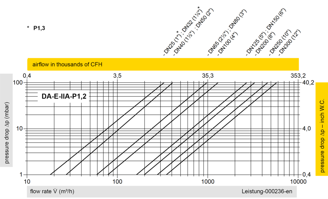
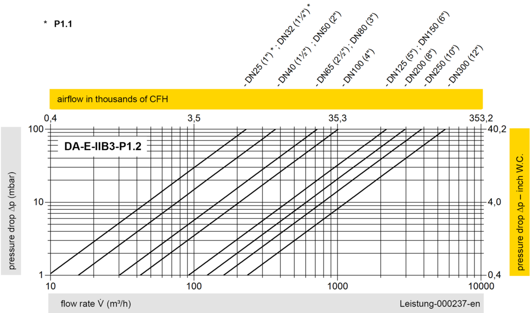
Los diagramas de flujo volumétrico han sido determinados con un banco de pruebas de caudal calibrado y certifi - cado por TÜV. El flujo volumétrico V. en [m³/h] y el CFH se refi eren a las condiciones estándar de referencia de aire según ISO 6358 (20°C, 1bar). La conversión a otras densidades y temperaturas están referidas en el Vol. 1: “Fundamentos Técnicos”.