DA-CG
In-Line Detonation Flame Arrester for unstable and stable detonations and deflagrations in a straight through design with shock absorber, bidirectional
- provides protection against deflagrations and stable and unstable detonations
- low number of FLAMEFILTER® discs due to shock absorber technology
- modular design enables individual cleaning and replacement of the FLAMEFILTER® discs
- different design allow scalable pressure loss over the area of the FLAMEFILTER®
- maintenance-friendly design
- available in large nominal widths
- advanced design for higher operating temperatures and pressures
- bi-directional operation, as well as any flow direction and installation position
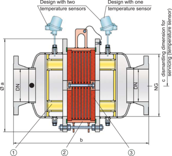
- installation of temperature sensors possible
- minimal pressure loss resulting in low operating and lifecycle costs
- cost-effective spare parts
Función y Descripción
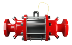
The PROTEGO® DA-CG series of detonation arresters was mainly developed for the North American market and optimized to meet the demands of the US Coast Guard. The devices are symmetrical and offer bi-directional flame arresting for deflagrations and stable and unstable detonations.
The effective shock absorber (1) greatly reduces the speed of incoming detonations. This leads to improved flame extinguishing in the narrow gaps of the FLAMEFILTER® (3).
The flame arrester essentially consists of two housing parts with an integrated shock absorber and the PROTEGO® flame arrester unit (2) in the center. The PROTEGO® flame arrester unit is modular and consists of several FLAMEFILTER® discs and spacers firmly held in a FLAMEFILTER® casing. The number of FLAMEFILTER® discs and their gap size depends on the arrester‘s intended use.
By specifying the operating conditions, such as the temperature, pressure, explosion group, and the composition of the fluid, the optimum in-line detonation flame arrester can be selected. Type PROTEGO® DA-CG flame arresters are available for explosion groups IIA to IIB3 (NEC group D to C MESG ≥ 0.65 mm).
The standard design can be used at an operating temperature of up to +60°C / 140°F and an absolute operating pressure acc. to table 3. Devices with special approvals for higher pressures and higher temperatures are available upon request.
The flame arresters have been approved in accordance with the American Standard 33 CFR part 154 and are accepted by the US Coast Guard.
Dimensiones
To select nominal width/nominal size (NG/DN) - combination, please use the flow capacity charts on the following pages. Additional nominal width/nominal size (NG/DN) - combinations for improved flow capacity upon request.
| NG | 150 / 6" | 150 / 6" | 200 / 8" | 300 / 12" | 400 / 16" | 500 / 20" | 600 / 24 | 700 / 28" | 800 / 32" | 1000 / 40" | 1200 / 48" |
| DN | ≤ 50 / 2" | 65, 80 / 2 ½“, 3 | ≤ 100 / 4" | ≤ 150 / 6" | ≤ 200 / 8" | ≤ 250 / 10" | ≤ 300 / 12" | ≤ 350 / 14" | ≤ 400 / 16" | ≤ 500 / 20" | ≤ 600 / 24" |
| a | 285 / 11.22 | 285 / 11.22 | 340 / 13.39 | 460 / 18.11 | 580 / 22.83 | 715 / 28.15 | 840 / 33.07 | 1025 / 40.35 | 1025 / 40.35 | 1255 / 49.41 | 1485 / 58.46 |
| b | 650 / 25.59 | 650 / 25.59 | 700 / 27.56 | 800 / 31.50 | 900 / 35.43 | 1100 / 43.31 | 1250 / 49.21 | 1500 / 59.06 | 1500 / 59.06 | 1700 / 66.93 | 2000 / 78.74 |
| c | 300 / 11.81 | 300 / 11.81 | 330 / 12.99 | 380 / 14.96 | 490 / 19.29 | 540 / 21.26 | 590 / 23.23 | 690 / 27.17 | 690 / 27.17 | 790 / 31.10 | 880 / 34.65 |
Selección de materiales para la vivienda
| Design | A | B |
| Housing | Steel | Stainless Steel |
| Gasket | PTFE | PTFE |
| Flame arrester unit | A | B |
Combinación de materiales para la unidad apagallamas
| Design | A | B |
| FLAMEFILTER® cage | Steel | Stainless Steel |
| FLAMEFILTER®* | Stainless Steel | Stainless Steel |
| Spacer | Stainless Steel | Stainless Steel |
Selección del grupo de explosión
| MESG | Expl. Gr. (IEC / CEN) | Gas Group (NEC) |
| > 0,90 mm | IIA | D |
| ≥ 0,65 mm | IIB3 | C |
Selección de la máxima presión de operación
| Expl. Gr. | DN | 50 / 2" | 80 / 3" | 100 / 4" | 150 / 6" | 200 / 8" | 250 / 10" | 300 / 12" | 350 / 14" | 400 / 16" | 500 / 20" | 600 / 24" |
| NG | 150 / 6'' | 150 / 6'' | 200 / 8'' | 300 / 12'' | 400 / 16'' | 500 / 20'' | 600 / 24'' | 700 / 28'' | 800 / 32'' | 1000 / 40'' | 1200 / 48'' | |
| IIA (D) | Pmax | 1,2 / 17.4 | 1,2 / 17.4 | 1,2 / 17.4 | 1,2 / 17.4 | 1,2 / 17.4 | 1,2 / 17.4 | 1,2 / 17.4 | 1,2 / 17.4 | 1,2 / 17.4 | 1,2 / 17.4 | 1,2 / 17.4 |
| IIB3 (C) | Pmax | 1,6 / 23.2 | 1,6 / 23.2 | 1,6 / 23.2 | 1,6 / 23.2 | 1,6 / 23.2 | 1,6 / 23.2 | 1,6 / 23.2 | 1,6 / 23.2 | 1,6 / 23.2 | 1,6 / 23.2 | 1,6 / 23.2 |
Especificación de la máx. temperatura de operación
| ≤ 60°C / 140°F | Tmaximum allowable operating temperature in °C |
| - | Designation |
Tipo de bridas de conexión
| EN 1092-1; Form B1 |
| ASME B16.5 CL 150 R.F. |
Modelo y especificación
There are three different designs available:
Basic design of the detonation arrester | DA-CG- – |
In-line detonation flame arrester with integrated temperature sensor* as additional protection against short time burning of one side | DA-CG- T |
Detonation arrester with two integrated temperature sensors* as additional protection against short time burning from both sides | DA-CG- TB |
Additional special arresters upon request
*Resistance thermometer for device group II, category (1) 2 (GII cat. (1) 2)
Diagrama de flujo volumétrico
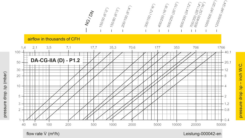
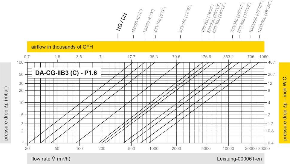
Los diagramas de flujo volumétrico han sido determinados con un banco de pruebas de caudal calibrado y certifi - cado por TÜV. El flujo volumétrico V. en [m³/h] y el CFH se refi eren a las condiciones estándar de referencia de aire según ISO 6358 (20°C, 1bar). La conversión a otras densidades y temperaturas están referidas en el Vol. 1: “Fundamentos Técnicos”.